
An eye-in-hand picking system needs more than an object detector connected to a motion command. Detection establishes the target, tracking updates its visible features, and the controller converts those measurements into bounded robot corrections. Calibration and timing determine whether those corrections move the gripper toward the intended grasp.
This explainer is for teams designing continuous camera-guided picking rather than taking a single image before a fixed move. You will learn how to separate the processing stages, choose a control representation, estimate an error budget, and handle unreliable observations without letting the tracker become a safety function.
Decide whether continuous correction is necessary
Use a visual servoing loop when the target can move, the initial position estimate is insufficient, or the approach requires repeated correction. A stationary, well-fixtured target may only need image acquisition, pose estimation, and a planned move followed by verification.
Continuous correction adds calibration, timing, and stability requirements. It is not automatically more accurate than a carefully commissioned measure-and-move sequence.
| Approach | Measurement schedule | Appropriate starting point | Main limitation |
|---|---|---|---|
| Measure and move | Before each planned move | Stationary targets with predictable placement | Cannot correct changes during the move |
| Image-based servoing | Repeated image-feature measurements | Maintaining visible feature alignment during approach | Depends on feature geometry and depth estimates |
| Position-based servoing | Repeated target-pose estimates | Tasks requiring explicit spatial pose control | Pose and calibration errors enter the command |
The coordinated sheet-alignment example addresses a different problem: measuring alignment and coordinating corrections between views. Here, camera motion changes the measurement continuously, so observation age and feedback behavior become central design concerns.
Separate detection, tracking, and control
Detection and tracking solve related but different problems. Detection identifies a candidate object and initializes its location or pose. Tracking maintains correspondence between observations, usually with less computation than repeatedly searching the whole image.
A practical processing chain is:
- Detect a permitted target and select its identity.
- Initialize features, a contour, or a pose tracker.
- Track those measurements in each usable frame.
- Check visibility, geometry, confidence, and measurement age.
- Calculate a correction only from accepted measurements.
- Send the correction through the robot's documented motion interface.
Do not treat a tracker confidence score as proof of correct identity. A tracker can remain confident while following a similar neighboring object. Check expected shape, feature arrangement, workspace location, and continuity of motion as well.
For acquisition candidates, start with area scan cameras and use the camera finder to filter the required interface and shutter type. The LS-MV-133GM-GE is a GigE, mono, global-shutter option. Its suitability still depends on application-specific acquisition timing and image quality.
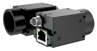
- Sensor format
- 1/2.7"
- Interface
- GigE
- Resolution
- Up to 3 MP
- Shutter
- Global
Keep detection recovery separate from normal tracking. Reinitialization should not silently select a different target while the robot continues its previous approach.
Choose the control representation before tuning
Image-based visual servoing controls errors in image features, such as corner coordinates, centroid location, or apparent feature size. Position-based visual servoing controls an estimated spatial pose relative to the desired grasp pose.
For image-based control, a common local relationship is:
Here, s contains measured image features, L is their interaction matrix, and v_camera contains translational and rotational camera velocity. The positive gain lambda sets the local correction rate. A damped inverse limits amplification near poorly conditioned configurations; it does not replace command limits or validation.
Some entries in the interaction matrix depend on target depth. Using an incorrect depth changes the relationship between image error and commanded motion. Feature layouts can also leave particular motion directions weakly observable.
Position-based control instead estimates the target pose and forms a translational and rotational pose error. It can express an approach direction clearly, but depends on reliable geometry and pose estimation.
Neither representation directly produces joint commands without further transformations. Convert the correction into the frame expected by the robot interface, then use its documented Cartesian control or inverse-kinematics path. Account for joint limits, singularities, and tool offsets independently of tracker confidence.
Calibrate the optical and mechanical coordinate frames
An eye-in-hand installation needs camera intrinsics, distortion calibration, the camera-to-tool relationship, and a defined grasp frame. The tool center point must also match the robot's configured tool.
Record each transform with an explicit direction, such as camera coordinates to tool coordinates. A matrix named only “hand-eye” invites an inversion mistake. Verify transform direction using a known displacement before allowing closed-loop motion.
Use calibration observations spanning the image area and the orientations expected during picking. Repeated views from nearly identical poses provide less geometric information than a varied set. Validate the resulting calibration on observations excluded from fitting.
Choose machine vision lenses around field of view, working distance, sensor coverage, and mechanical clearance. The lens finder and focal-length selection guide help establish the optical starting point.
The LS-SMV2528P-6M is a C-mount machine vision lens. Treat it as an optical candidate, not a prevalidated pairing for every camera or picking distance.
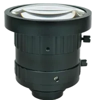
- Type
- Machine vision fixed
- Sensor format
- 2/3"
- Mount
- C-mount
- Resolution
- 6-10 MP
Lock focus and mounting adjustments after calibration. If the camera bracket moves or the optical configuration changes, reassess calibration before resuming automatic operation.
Work through a pixel-to-motion error budget
A simplified pinhole model gives a useful estimate of lateral target error near the optical axis. It assumes known depth, corrected distortion, and a displacement approximately parallel to the image plane.
Suppose the target depth is 600 mm, the calibrated horizontal focal length is 1200 pixels, and the horizontal image error is 24 pixels:
This is an estimated geometric error, not permission to issue an immediate move of that size. Depth uncertainty, camera rotation, perspective, and tool geometry can invalidate the simplified interpretation.
For a separate sampling check, suppose the horizontal field of view is 120 mm across 2400 pixels:
The camera resolution calculator supports this sampling calculation. Sampling is not the same as positioning accuracy: lens distortion, feature contrast, calibration, motion, and estimation noise still contribute errors.
Do not combine this sampling example with the previous depth example as though they describe one optical setup. Each demonstrates a different calculation that must ultimately use measurements from your actual installation.
Align exposure timestamps with robot state
The relevant measurement time is the exposure event, not the moment an application finishes processing the image. Transport, buffering, tracking, and command transmission all add delay.
Associate every accepted observation with its acquisition timestamp and frame identifier. For moving cameras, associate the corresponding robot pose as well. If clocks differ, establish their offset and drift using a documented synchronization method or a measured timing relationship.
Exposure timestamp definitions vary. Confirm whether the timestamp refers to exposure start, another acquisition event, or a device-specific event. For geometric association, account for the exposure interval and choose a consistent representative time.
Consider an illustrative approach speed of 10 mm/s and an observation age of 80 ms:
Under the earlier simplified projection, that lateral travel would correspond to approximately 1.6 pixels. More importantly, it could exceed the allowed grasp-position error even while images appear smooth.
Use the external-trigger timing guide when planning acquisition events. The per-frame metadata verification guide explains why requested exposure settings should be distinguished from settings associated with an acquired frame.
A high display rate does not establish a low-delay control path. Measure the complete exposure-to-command interval and reject observations older than the commissioned limit.
Bound commands and define target-loss behavior
Use only robot interfaces documented for the intended external-control mode. Keep command ownership explicit so the vision process and another motion source cannot compete unexpectedly.
Limit translation, rotation, acceleration, and permissible workspace through the appropriate control layers. Express each limit in a named coordinate frame. A small camera-frame correction can still produce an undesirable tool motion if the camera and gripper are offset.
For illustration, a controller updating at 20 Hz with a translation increment capped at 0.5 mm has an implied incremental speed ceiling of 10 mm/s. That arithmetic is not a safe-speed recommendation. The actual limits depend on the robot, tooling, payload, stopping behavior, and application risk assessment.
Define normal and failure states before tuning:
- Acquire: select and validate the intended target without automatic approach motion.
- Align: apply bounded corrections while monitoring convergence and visibility.
- Approach: maintain the required feature geometry and clearance while progressing toward the grasp.
- Verify: require acceptable pose or feature error, freshness, and stability before grasp execution.
- Lost target: cancel stale corrections and request the documented controlled hold or stop behavior.
- Recover: require fresh target validation and an explicit transition before motion resumes.
The motion interface should have a suitable command timeout or watchdog. Reusing the last velocity command indefinitely after image loss is not acceptable recovery behavior.
Select processing hardware by measured workload
The processing platform must sustain acquisition, tracking, validation, logging, and robot communication together. Benchmark the intended image format and algorithm, not just an isolated detection demonstration.
Measure processing-time distributions and worst observed observation age during representative load. Background logging, network traffic, and recovery detection can create longer delays than normal tracking.
Browse vision controllers when camera connectivity and integrated processing are part of the architecture. The MV-VC2101-128G40-NN is a vision-controller candidate for evaluating the processing stage. Confirm required interfaces, software compatibility, and communication provisions before selecting it.
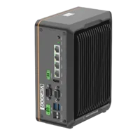
- LAN ports
- 3-4 LAN ports
- USB 3 ports
- 2 USB 3 ports
- Memory
- 16 GB
- Processor
- Intel N-series
The camera, lens, and controller shown here are evaluation candidates, not a qualified control package. Their inclusion does not establish end-to-end latency, robot compatibility, calibration accuracy, or safety capability.
If acquisition becomes intermittent, resolve that fault before increasing control gain. The acquisition-failure troubleshooting guide provides a separate diagnostic path for missing or inconsistent images.
Commission the loop with recorded evidence
Begin with offline playback and command calculation disabled from motion output. Confirm that feature errors, timestamps, frame transformations, and proposed corrections behave consistently across recorded sequences.
The preview-overlay debugging guide is useful for displaying target identity, feature residuals, measurement age, and proposed correction direction. Keep the control data separate from display refresh timing.
Then perform controlled commissioning under the robot manufacturer's documented procedures and the application's approved safeguarding arrangements. Check these items before increasing operating demands:
- Correction direction: a known displacement produces a command that reduces the intended error.
- Axis coupling: camera rotation and translation do not create unexplained cross-axis motion.
- Convergence: errors decrease without persistent oscillation or command saturation.
- Visibility: approach motion does not hide the features needed for control.
- Target identity: adjacent objects cannot silently replace the selected target.
- Observation freshness: delayed frames are rejected rather than treated as current measurements.
- Failure response: occlusion, frozen images, communication loss, and process termination produce the specified controlled response.
- Grasp transition: closing the gripper occurs only after the separately defined acceptance conditions are met.
Record both successful runs and failure cases. Passing one centered approach does not establish performance across the full picking envelope.
Recognize when the usual approach is wrong
A tracker-driven loop is a poor fit when the target lacks stable features, reflective appearance changes dominate the image, or the gripper obscures the target before useful alignment is complete. Improve lighting, feature selection, or camera placement before compensating with higher gain.
A single monocular view may also lack enough information for the required spatial correction. Known object geometry, depth sensing, an additional view, or a constrained motion plan may be necessary. More image pixels cannot resolve an unobservable motion direction by themselves.
Before ordering, define the grasp tolerance, visibility envelope, acquisition timing, required robot interface, and target-loss response. Use the camera configuration starting point to organize acquisition choices, or contact the applications team with representative images, working distances, timing measurements, and the intended control architecture.
Questions
Can one algorithm handle detection, tracking, and visual servoing?
They can belong to one software pipeline, but they perform different jobs. Detection establishes target identity, tracking updates measurements, and control converts accepted measurements into motion requests. Keeping explicit interfaces between these stages makes timing faults, incorrect correspondence, and recovery behavior easier to diagnose.
Should eye-in-hand picking use image-based or position-based control?
Image-based control is useful when reliable image features describe the desired alignment. Position-based control is useful when the task needs an explicit spatial target pose and that pose can be estimated consistently. Compare visibility, depth information, calibration sensitivity, and robot-interface requirements before choosing either approach.
What camera frame rate does a visual servoing loop need?
There is no universal minimum. Required update rate depends on target motion, robot speed, exposure duration, processing delay, and allowed error. Measure observation age and timing variation across the complete pipeline. A slower stream with predictable timing may be more useful than a faster stream carrying delayed measurements.
What should happen when the tracker loses the target?
Rejected or missing observations should prevent further stale corrections and initiate the documented controlled response. Recovery should validate a fresh target and deliberately re-enter the permitted motion state. Personnel protection must remain with the machine's independently designed safeguarding and safety-rated functions.
Does eye-in-hand visual servoing always require a depth camera?
Not necessarily. A planar alignment task may operate with constrained geometry, while general spatial picking needs adequate depth or pose information. Known object dimensions, an additional view, or a depth sensor may provide that information. The decision depends on which motion directions must be observed and controlled.