
A printed chessboard can produce a useful camera calibration, but a successful corner detector does not prove the target geometry is correct. Wrinkles, uneven mounting and printing distortion can all introduce errors that the calibration solver cannot distinguish cleanly from camera behavior.
This matters when you move from making images look straight to measuring dimensions or locating parts within a specified tolerance. You will need to decide whether mounted paper is adequate, identify the errors that matter, and verify the result against something other than the target used to calculate it.
Choose the target from your measurement tolerance
Start with the result you need, not the target material. Removing obvious barrel distortion for an operator display is a different task from measuring a feature near the image edge.
Write down the permitted measurement error, the field of view and the range of object heights. Then allocate part of the error budget to calibration. Lighting, edge localization, mechanical motion and reference uncertainty also need room in that budget.
| Requirement | Sensible starting point | What must be verified |
|---|---|---|
| Visually straightened images | Flat, securely mounted paper | Straight features remain straight throughout the useful image |
| Part localization with moderate tolerance | Mounted paper with checked printing and mounting | Position errors at the center, edges and operating heights |
| Dimensional measurement with a tight error budget | A rigid target with documented geometry and uncertainty | Independent measurement errors remain within the allocated budget |
| Repeated calibration across machines or over time | A stable target with identified geometry and handling controls | Calibration results remain consistent after repositioning and reuse |
Rigid does not automatically mean accurate. A stiff panel can be bowed, and a precise printed pattern can distort when bonded to it. Evaluate the completed target assembly, including its mounting method.
For systems where changing part height is a major error source, when you need a telecentric lens for gauging explains the relevant imaging geometry. Telecentric imaging reduces perspective-related scale changes, but does not make an inaccurate calibration reference trustworthy.
How wrinkles violate the planar model
A planar calibration assigns each target corner a known position on a flat surface. The solver then estimates camera parameters and the target pose that best explain the observed image coordinates.
A wrinkle moves some corners away from that assumed plane. The camera sees the displaced physical points, while the solver receives coordinates for an ideal flat pattern. That disagreement can affect estimated pose, focal length and distortion.
Perspective projection also explains why distance and image position matter. A local displacement along the optical axis changes the apparent position of an off-axis point. Field of view, working distance and image sampling therefore belong in the assessment.
For a nominally front-facing target, consider a small local displacement along the optical axis. Ignoring lens distortion, a first-order estimate is:
Here, u is the horizontal image coordinate, cx is the principal-point coordinate, and f_px is focal length expressed in pixels. X and Z are camera-coordinate distances. The estimate assumes the point's lateral coordinate stays fixed and the displacement is small compared with distance.
Suppose a corner lies 800 pixels from the principal point, the target is 400 mm away, and a wrinkle displaces that corner by 0.5 mm along the optical axis:
That is a projection sensitivity estimate, not a prediction of final calibration error. A real wrinkle can also move corners sideways, and tilted views change the geometry. The fitting process can distribute the mismatch among several parameters.
Separate printing errors from detection reliability
Flatness is only one property of a usable target. Check the printed pattern before spending time improving the mounting.
Measure long spans across several squares in both directions. Long spans reduce the relative influence of reading uncertainty compared with measuring one small square. Also compare spans near opposite edges to look for nonuniform printing.
For example, suppose a nominal span should measure 200 mm. If the horizontal span measures 198 mm while the vertical span measures 200 mm, the horizontal scale error is:
That unequal scaling changes the assumed target geometry. Disable automatic print fitting and verify the physical result rather than trusting the document dimensions.
Uniform scaling has a different consequence. In an ideal monocular planar calibration, scaling all target dimensions equally changes the scale of estimated translations rather than focal length in pixels or distortion. However, using that incorrect spacing as a metric reference still transfers its scale error into measurements.
Detection reliability is a separate issue. A clear surrounding border, sharp transitions and suitable exposure help the detector find and order corners. Follow the detector's documented pattern and border requirements.
A target can be easy to detect but geometrically wrong. Conversely, a well-made target can fail detection because of glare, blur, clipping or an unsuitable pattern layout.
Work backward from an error budget
Consider an illustrative inspection covering 120 mm across 2400 image pixels. Its nominal horizontal object sampling is:
Use the camera resolution calculator to explore the relationship between field coverage, feature size and image sampling. Sampling alone does not establish measurement accuracy.
Suppose the application permits an error of ±0.10 mm, and you allocate 0.025 mm to the combined effects of calibration-target geometry and model fitting. That allocation is an engineering choice for this example, not a universal rule.
At the nominal sampling above, the allocated error corresponds to:
Using the earlier front-facing sensitivity estimate, a corner offset of 800 pixels and a target distance of 400 mm give:
This calculation tells you that a visible wrinkle deserves attention in this example. It does not establish a purchasing specification for target flatness. Printing errors, target tilt, local stretching and fitting behavior remain outside this simplified estimate.
Use the arithmetic to screen target choices, then use independent measurements to accept the calibration. For another working distance, field of view or tolerance, repeat the calculation rather than reusing the result.
Capture views that test the geometry
A large image count cannot compensate for nearly identical views. The solver needs useful changes in target position and orientation to constrain the camera model.
Build a capture set with these properties:
- Cover the center, sides and corners of the image, rather than keeping the pattern centered throughout.
- Include tilts about different target axes, while retaining sharp and reliably detected corners.
- Keep the entire required pattern visible and follow the detector's visibility requirements.
- Use a stationary target and camera during each exposure. Motion can distort corner positions, especially with rolling-shutter acquisition.
- Reject images with glare, clipping, defocus or ambiguous corner ordering.
- Keep focus, aperture and acquisition settings controlled throughout the sequence.
Tilting the target is useful; bending it is not. Support it so that changing its orientation does not change its shape. Avoid clamping forces that introduce bowing.
Exposure changes can alter the appearance of printed boundaries. The guide to automatic iris, exposure and gain control explains those controls; for repeatable calibration, use stable settings that preserve usable contrast without clipping.
Record the image dimensions, crop, focus setting and target geometry with the result. Changes to focus, acquisition geometry or camera-lens mounting require reassessment rather than an assumption that the old parameters still apply.
Read reprojection error without overtrusting it
Reprojection error compares detected corner positions with positions predicted by the fitted camera model. It is useful for identifying poor captures and inconsistent data, but it is not an independent measurement of physical accuracy.
A low residual can coexist with an incorrect target. The solver may partly explain target deformation through pose or distortion parameters. Adding model parameters can reduce fitting error without improving measurements elsewhere.
Review more than one aggregate value:
| Check | What it can reveal | What it cannot establish alone |
|---|---|---|
| Overall reprojection error | Broad consistency of the fitted observations | Correct target dimensions or absolute measurement accuracy |
| Error by image | Blur, bad detections or problematic poses | Whether all images share the same systematic target error |
| Residual vectors across the image | Spatial patterns suggesting model mismatch | A unique diagnosis of the underlying cause |
| Held-out target images | Performance on poses excluded from fitting | Independent geometry, if the same distorted target is reused |
| Repeated calibration sessions | Sensitivity to mounting, captures and target handling | Absolute accuracy without a separate reference |
Do not increase distortion-model complexity solely to reduce a residual. Use a model appropriate to the lens and software, then check whether it improves independent results.
A straight-looking corrected image is similarly limited evidence. It can be sufficient for display correction, but does not prove that dimensions or positions meet a tolerance.
Validate with an independent reference
Choose a reference whose geometry and uncertainty are known independently of the calibration pattern. Reusing the same assumed square spacing to validate scale creates a circular check.
For planar measurement, place the reference at the actual inspection plane. Measure features near the image center and all four corners of the useful field. Include different orientations where the application measures both horizontal and vertical dimensions.
Repeat the acquisition and reference placement across at least three rounds as a practical repeatability check. Keep signed error as well as absolute error: consistent positive or negative errors can reveal bias that a repeatability figure hides.
Record:
- The known reference value and its uncertainty.
- The measured value at each image location.
- Signed error, maximum absolute error and variation between repetitions.
- Object height, camera settings and the correction method used.
If production parts vary in height, validate across that height range. Intrinsic calibration and lens-distortion correction do not remove the perspective scale change caused by moving an object toward or away from a conventional lens. A planar mapping applies to its defined plane.
Accept the result only when independent errors fit the allocated budget, with reference uncertainty considered. If the check fails, change one factor at a time: target geometry, mounting, capture coverage or camera model.
Choose acquisition hardware without confusing it with target quality
You do not necessarily need another camera or lens to resolve a calibration problem. First determine whether the limitation is target geometry, image quality or the selected mathematical model.
When selecting area scan cameras, use the camera finder to match image sampling, shutter behavior and interface requirements. The LS-MV-133GM-GE is a monochrome, global-shutter GigE camera option with a C-mount.
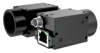
- Sensor format
- 1/2.7"
- Interface
- GigE
- Resolution
- Up to 3 MP
- Shutter
- Global
Select machine vision lenses for sensor coverage, working distance, field of view and usable image quality. The LS-SMV2528P-6M is a C-mount machine vision lens option.
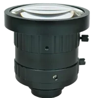
- Type
- Machine vision fixed
- Sensor format
- 2/3"
- Mount
- C-mount
- Resolution
- 6-10 MP
Neither example establishes a calibration accuracy specification. Review the lens finder and how to choose a machine vision lens focal length when defining the optical arrangement, then validate the completed assembly at its operating settings.
Check before keeping paper or ordering a rigid target
Mounted paper is a reasonable choice when its geometry is sufficiently stable and independent validation passes. Keep it supported, protected from handling damage and identified so that later calibration sessions use the correct dimensions.
Before accepting the target, check:
- Print geometry: verify long spans in both directions and inspect for local stretching.
- Mounted flatness: inspect the completed assembly, including edges and clamped regions.
- Surface appearance: avoid glare, translucent backing effects and damaged corner boundaries.
- Capture coverage: include varied poses and the full useful image region.
- Independent accuracy: validate known dimensions or positions at application locations and heights.
- Repeatability: repeat the process after repositioning the target and compare results.
Choose a rigid, characterized target when the error budget is too small to verify paper adequately, when the mounting changes shape during use, or when repeated sessions need better geometric stability. Request information about pattern geometry, flatness, uncertainty and mounting conditions rather than material alone.
If independent measurements already meet the requirement, replacing paper may add little practical value. If they fail, a more expensive target is not automatically the answer; isolate the error before ordering.
Define your field of view and tolerance in the lens configuration step, or send the target dimensions, working distance and validation results through technical support to discuss the next checks.
Questions
Can a paper chessboard be accurate enough for camera calibration?
Yes, when it is mounted securely, its printed geometry is checked, and independent measurements meet the application's error budget. A paper target is not disqualified by its material alone. Its suitability depends on the completed assembly, capture conditions and required measurement performance.
How flat does a camera calibration target need to be?
There is no universal flatness limit. The effect depends on camera distance, corner position, target orientation and the required accuracy. Estimate image displacement from plausible surface deviations, then validate against a separate reference. Specify flatness together with pattern geometry and mounting conditions rather than treating it as an isolated requirement.
Does a low reprojection error prove that the target is accurate?
No. That value measures agreement between detected image points and the fitted model. Systematic target errors can partly enter the estimated camera parameters. Use residuals to diagnose the fit, but use independently known dimensions or positions to judge whether the calibration is suitable for measurement.
Does adding a white border make calibration more accurate?
A clear border can improve pattern recognition and reduce failures near the target boundary. It does not straighten a warped board or correct inaccurate square spacing. Follow the detector's documented layout, then assess corner localization and physical target geometry as separate parts of the calibration process.
When should a rigid target replace mounted paper?
Use a rigid target when paper cannot remain stable during capture, when repeated sessions must reproduce geometry reliably, or when the measurement budget requires characterized target uncertainty. Ask for evidence about the finished pattern and surface geometry; stiffness by itself is not evidence of dimensional accuracy.