
Two sequential pickups followed by one paired placement require more than switching between vacuum channels. The controller must know which target belongs to each cup, whether each cylinder has retracted, and whether both objects remain attached. This explainer is for teams defining that sequence before commissioning. You will learn how to separate pneumatic commands, manage target ownership, synchronize process events with motion, and handle missing feedback without bypassing machine safety.
1. Choose a gripper state machine, not an output sequence
Use one coordinated state machine for the complete tool, with separate status records for cup A and cup B. Permit paired placement only after both records confirm a successful pickup and retraction.
Each cup record should contain:
- Assigned target identifier and conveyor reference.
- Cylinder command and measured position.
- Vacuum command and measured holding condition.
- Occupancy state: empty, acquiring, loaded, releasing or uncertain.
- Current timeout and diagnostic reason.
Commanded state is not measured state. An extend output does not prove that a cylinder reached its working position. Likewise, enabling vacuum does not prove that an object is attached.
The coordinator decides when motion may proceed. Separate cup logic handles the pneumatic actions and reports completion or failure. This structure prevents cup B from starting merely because a fixed delay after cup A has elapsed.
The existing explanation of overlapping vision processing and motion covers when to request another result. Here, the additional requirement is ownership: a result must belong to a particular cup until its pickup outcome is resolved.
2. Map cylinder, vacuum and blow-off functions separately
Start with the pneumatic schematic and the documented machine I/O configuration. Do not infer cylinder functions from existing vacuum or blow-off output assignments.
A logical interface might look like this:
| Function | Logical command | Feedback or verification |
|---|---|---|
| Cup A cylinder | Extend or retract request | Extended and retracted position sensors |
| Cup B cylinder | Extend or retract request | Extended and retracted position sensors |
| Cup A holding circuit | Vacuum enable | Vacuum switch or documented grip confirmation |
| Cup B holding circuit | Vacuum enable | Vacuum switch or documented grip confirmation |
| Cup A release circuit | Blow-off request, if fitted | Release confirmation appropriate to the process |
| Cup B release circuit | Blow-off request, if fitted | Release confirmation appropriate to the process |
These are logical functions, not a universal wiring diagram. A spring-return valve may use one electrical command, while another arrangement may require separate valve commands. The valve documentation determines coil behavior, permissible combinations and behavior after power loss.
Keep vacuum and cylinder commands independent unless the tool manufacturer explicitly provides an integrated function. Retracting a cylinder must not unintentionally remove holding vacuum.
3. Define transitions with feedback guards
The following table describes a normal cycle. A transition occurs only when its guard is satisfied; a timeout leads to a defined exception state.
| State | Main action | Guard before advancing |
|---|---|---|
| Ready | Check tool and tracking readiness | Both cups empty, cylinders retracted, required references valid |
| Acquire A | Reserve a target and approach with cup A | Target reachable; cup B remains in its required clearance state |
| Pick A | Extend A and apply vacuum as configured | A pickup confirmation accepted |
| Retract A | Retract while maintaining holding vacuum | A retracted and holding condition acceptable |
| Acquire B | Reserve another target and approach with cup B | A remains loaded; B target reachable |
| Pick B | Extend B and apply vacuum as configured | B pickup confirmation accepted |
| Retract B | Retract while maintaining both holding circuits | Both required retraction and holding conditions satisfied |
| Place pair | Track the destination and execute release | Destination valid; both objects presented at the required pose |
| Confirm empty | Verify release and retract the tool | Both cups empty and required retraction feedback present |
The placement state may contain additional sub-states for extension, contact and release. Their order depends on the tool geometry and placement process.
A pickup confirmation can combine several observations, such as vacuum level and cylinder position. Define acceptable combinations explicitly rather than treating any single active input as success.
Latch the fault reason and relevant target identifiers when a transition fails. Otherwise, a later input change can erase the evidence needed to explain the interruption.
4. Assign targets using cup-specific geometry
The two cups have different offsets from the robot tool reference. Use the calibrated transform for the selected cup when calculating its pickup pose. Reusing the same pose without compensating for cup offset can move the wrong cup over the target.
Store targets by identity, not merely by their order in a changing detection list. A practical lifecycle is:
- Detect and timestamp the object.
- Check that its tracking data remain valid.
- Reserve it for cup A or cup B.
- Attempt the pickup.
- Mark it consumed after the configured success confirmation.
- Release the reservation only after resolving a failed attempt.
After an ambiguous pickup, do not automatically return the target to the available queue. The object might have moved, attached briefly or left the camera view.
The destination must also accommodate the complete pair. Check cup spacing, object dimensions, orientation and clearance against the reserved placement footprint.
Use the two-line conveyor tracking configuration guide when separating pickup and placement conveyor references. The stale conveyor vision data troubleshooting guide helps distinguish an ownership error from an outdated target pose.
5. Synchronize events with motion, then verify the result
Use the motion controller's documented position- or path-synchronized event mechanism where an output must occur at a defined motion location. Confirm its supported motion types, tracking behavior, event lifetime and interruption behavior in the applicable documentation.
A general-purpose software timer is not equivalent to a path event. Changes in approach speed, blending or tracking can shift where a timer expires.
However, an accurately scheduled electrical command still precedes a delayed physical action. A simplified timing estimate is:
This is a commissioning estimate, not a guaranteed compensation model. Electrical delay, pressure, tubing, valve response and object sealing can change the result. Measure the command and physical response under representative conditions.
Schedule cylinder extension only within a validated approach region. Timing compensation must not extend a cup early into an obstruction or replace a required position check.
Also distinguish simultaneous commands from simultaneous release. Both channels can receive one coordinated release request yet detach their objects at different times. Specify the acceptable release skew and verify it physically.
If release timing requires feedback resolution finer than the controller provides, change the instrumentation or mechanism. Do not claim simultaneity from equal output timestamps alone.
6. Calculate cycle time and remaining tracking time
Build the timing budget from measured state durations. The following values are hypothetical application measurements, not specifications for any listed product:
| Cycle element | Assumed duration |
|---|---|
| Approach and acquire A | 0.35 s |
| Confirm and retract A | 0.08 s |
| Approach and acquire B | 0.35 s |
| Confirm and retract B | 0.08 s |
| Transfer to placement | 0.45 s |
| Place and confirm release | 0.12 s |
| Return to pickup readiness | 0.40 s |
For this non-overlapped example:
This estimate excludes waiting for suitable targets, recovery, rejected destinations and production interruptions. Do not use it as a guaranteed sustained rate.
Check the second target's remaining tracking window separately. For constant conveyor speed:
If acquiring and retracting the second cup requires 0.43 s, the arithmetic leaves 1.20 − 0.43 = 0.77 s. That remaining interval must cover any additional required motion and validated allowance before the target exits the usable region.
Repeat the check for the placement conveyor using its own reference and available destination window. If target spacing creates long waits, the conveyor target availability guide addresses the resulting cycle losses.
7. Treat partial pickup as a separate operating condition
A loaded cup A with an empty cup B is neither an empty tool nor a valid pair. Define what happens before production begins.
Possible policies include holding the first object while requesting another reachable target, transferring it to a designated recovery location, or entering a controlled stop. The permitted choice depends on retention capability, available space and the machine risk assessment.
For each failure, define a specific response:
- No vacuum confirmation: stop advancing the pickup sequence and determine whether the target remains available.
- No retracted feedback: inhibit motion that assumes retracted clearance and enter the documented exception response.
- Holding condition lost during transfer: invoke the assessed response without assuming the object remains attached.
- Destination becomes invalid: preserve object identity and follow the defined loaded-tool recovery path.
- Release remains uncertain: do not mark both cups empty merely because vacuum commands are off.
A vacuum switch may indicate an evacuated circuit even when the release outcome remains ambiguous. Choose confirmation appropriate to the failure being detected.
After interruption or restart, reconcile actual tool occupancy with stored target records before resuming. The conveyor vision startup synchronization guide covers the related need to restore valid tracking references.
8. Select components by verified interfaces
The state machine can be distributed across a motion controller, a vision device and supervisory logic. Assign one owner for each transition so that two devices cannot independently advance the same cycle.
The MV-SVC2506-16G60-128G is a vision-controller candidate. Confirm application compatibility, communication behavior and the division of responsibility with the motion controller before selection.
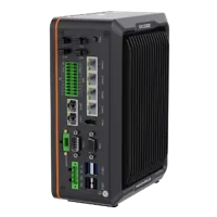
- LAN ports
- 5+ LAN ports
- USB 3 ports
- 2 USB 3 ports
- Light outputs
- 4 built-in channels
- Memory
- 16 GB
The MV-SC3013XM-12M-ATN-H is a vision-sensor candidate. Validate the inspection task and how target identifiers, poses and acquisition timing reach the tracking system.
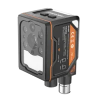
- Interface
- GigE
- Resolution
- Up to 3 MP
- Sensor format
- 1/1.45"
- Shutter
- Global
The MV-PE5502 is a diffuse-reflective sensor with an NPN output. Confirm electrical compatibility and detection performance for the intended part-present task.
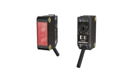
- Output
- NPN
- Light source
- Red LED
- Sensing range
- 100 mm - 1 m
- Type
- Diffuse-reflective
A part-present sensor does not replace cylinder position feedback or vacuum confirmation. Those functions require their own suitable sensing arrangements.
Compare vision controllers by the interfaces your architecture requires. Review smart cameras and vision sensors through the camera finder, and compare photoelectric sensors in the trigger sensor finder. None of these selections establishes motion-event compatibility without checking the documented integration.
9. Commission with a state-by-state checklist
Commission under the machine's approved procedures, with safeguarding operational. Begin at controlled operating conditions and expand testing only after each stage passes.
- Verify output mapping: confirm each command operates the intended valve function without affecting the other cup.
- Verify feedback meaning: check extended, retracted, holding and empty indications against the physical tool.
- Check geometry: validate both cup offsets and the loaded-tool envelope throughout approach and transfer.
- Trace target ownership: log target identity, cup assignment, reservation, success and placement outcome.
- Measure response: record command times, feedback times, conveyor positions and motion-event locations.
- Exercise exceptions: use an approved test method to check missing pickup, missing retraction and invalid-destination handling.
- Test restart: confirm recovery does not reuse stale targets or assume an uncertain cup is empty.
- Validate paired release: measure placement error and release skew against the process acceptance limits.
Record normal timing variation before selecting timeouts. A timeout should distinguish an abnormal response from legitimate variation; it should not conceal slow or inconsistent pneumatic behavior.
10. Know when paired placement is the wrong approach
Sequential acquisition works best when the first object can remain securely held while the second is collected. It becomes less attractive when target gaps vary widely, retention time is limited, or the loaded first cup obstructs the second pickup.
Simultaneous placement also requires compatible destination geometry. If the destination spacing differs from fixed cup spacing, software timing alone cannot correct the mechanical mismatch.
Consider independent placement, an adjustable tool or a revised material flow when pairing creates excessive waiting or unreliable clearances. Keep the acceptance criteria explicit: valid ownership, confirmed holding, required cylinder positions and a reachable destination.
For component selection, start with the trigger configuration step. For integration help, send the tool schematic, I/O list, tracking arrangement and measured timing budget through applications support.
Questions
Can the existing vacuum outputs also operate the cylinders?
Not necessarily. Cylinder valves, vacuum valves and blow-off valves perform different functions, even when mounted together. Determine the required electrical commands from the pneumatic schematic and valve documentation. Existing vacuum output assignments do not establish how either cylinder extends, retracts or behaves after power loss.
Are fixed delays enough between the two pickups?
Fixed delays can support diagnostics or a documented process, but elapsed time alone does not establish cylinder position or successful holding. Use suitable feedback and bounded timeouts for sequence transitions. Validate delay settings across the expected pressure, load and operating conditions rather than relying on a single successful cycle.
Does switching both vacuum channels together guarantee simultaneous release?
Equal command timestamps establish coordinated electrical requests, not equal physical detachment times. Valve response, tubing, seal behavior and object adhesion can differ between channels. Define an acceptable release-time difference and measure the actual release behavior using instrumentation suitable for that tolerance.
What should happen if only the first cup picks successfully?
Treat the tool as partially loaded and preserve the identity of the object already acquired. Follow a predefined recovery policy, such as another reachable pickup attempt or transfer to a designated recovery location. The policy must account for holding capability, tracking validity, clearance and the assessed machine hazards.
Does a smart camera replace the gripper sequence controller?
No. Vision can provide object location and identification, but it does not automatically establish valve operation, cylinder position or holding condition. Integrate the required tool feedback with a clearly owned state machine, and verify communication and motion-event compatibility against the applicable equipment documentation.