
Repeated conveyor starts and stops can interrupt an otherwise steady picking process. For a controls team, the better approach may be to adjust belt speed around the number of usable targets waiting for collection. That requires more than counting detections in each image. You need a defined queue, a verified relationship between speed and arrivals, and a PLC strategy that respects motion limits. The following approach separates those tasks and explains how to commission them without blocking image acquisition or robot execution.
Define the queue before controlling speed
Use the number of valid, unpicked targets available to the picking process, not the number of objects visible in the latest camera image. A useful queue entry represents a distinct tracked object that remains eligible for collection.
Your occupancy calculation should exclude:
- Duplicate detections of an existing target.
- Rejected objects and targets with invalid coordinates.
- Targets already picked or removed from service.
- Objects outside the usable tracking region.
- Targets reserved by another robot, unless your queue definition explicitly includes reservations.
Record reserved targets separately when several robots share work. Otherwise, a large reported queue can hide the fact that almost nothing remains assignable.
Also distinguish tracked from currently reachable. An upstream target may be valid but not yet inside a robot's picking window. Keep these populations separate if their difference materially affects your controller.
The closest supporting guide, diagnosing conveyor target availability, explains why queue totals and available work can differ. Establish that distinction before introducing speed feedback.
Check whether belt speed controls replenishment
The proposed control direction is simple: increase speed when the queue is low and reduce speed when it is high. However, that direction is correct only when higher speed increases usable arrivals enough to replenish the queue.
For a simplified queue model:
Here, target density is measured in targets per metre, speed in metres per second, and arrival rate in targets per second. This estimate assumes reasonably uniform spacing and that the camera admits each physical target once.
Changing speed also changes travel time and remaining picking time. It may affect the successful pick rate, particularly when robot tracking limits become significant. A smaller queue therefore does not automatically mean better operation: it could indicate targets leaving the workspace unpicked.
Measure successful picks, missed targets, invalidations and queue occupancy together. Use conveyor scene timing checks when target age or position appears inconsistent with the belt.
Build a bounded controller with hysteresis
Start with discrete speed levels rather than an aggressive continuously varying controller. They make the response easier to observe and reduce unnecessary command changes.
A commissioning example might use the following states. These are application assumptions, not equipment specifications.
| State | Entry condition | Requested speed | Return condition |
|---|---|---|---|
| Replenish | Queue at or below 12 targets | Faster validated speed | Return to normal at 16 targets |
| Normal | Recovery from either outer state | Nominal validated speed | Leave at either outer threshold |
| Drain | Queue at or above 20 targets | Slower validated speed | Return to normal at 16 targets |
Within each hysteresis band, retain the current state. Do not switch directly between faster and slower commands every time the count changes by one target.
Evaluate the latest status periodically, but apply speed changes through an acceleration-limited request. Clamp every request to the validated operating range, even if the software calculation produces something outside it.
A general command structure is:
If you later replace the state table with proportional feedback, a possible structure is:
The sign assumes increasing speed replenishes the queue. Apply the same bounds, freshness checks and slew limits afterward. Do not add integral action until the basic response, transport delay and saturation behavior are understood.
Work through the rates and delays
Assume an illustrative line has a target density of 2 targets/m and a successful picking capacity of 1.2 targets/s. Choose nominal, faster and slower speeds of 0.6 m/s, 0.7 m/s and 0.4 m/s respectively.
At nominal speed:
At the faster setting, arrivals become 1.4 targets/s. If picking capacity remains unchanged, the queue grows by approximately 0.2 targets/s. Recovering from 12 to 16 targets would take:
At the slower setting, arrivals become 0.8 targets/s. The estimated queue reduction is 0.4 targets/s. Reducing a queue from 24 to 20 targets would take:
These estimates exclude acceleration, transport delay, target losses and variations in pick time. They show why a controller should not reverse its decision merely because the queue has not changed after one update.
Suppose replenishment has a measured delay of 3 s. At the faster setting, approximately 1.4 × 3 = 4.2 targets can arrive during that interval. Allowing capacity for at least 5 additional targets would cover those expected arrivals if picking suddenly paused, before adding variability margin. This is a buffer-sizing estimate, not a safety calculation.
For an acceleration limit of 0.1 m/s², changing from 0.6 m/s to 0.4 m/s requires at least:
Verify that this ramp suits the drive, conveyed material, tracking system and machine design. A software request limit alone does not establish the drive's actual ramp behavior.
Transfer status without blocking execution
Keep queue measurement separate from potentially slow communication. A periodic task should read a documented queue interface and copy a compact snapshot into a shared status structure. It should not wait for a serial reply, socket connection or acknowledgement.
A separate communication task can publish that snapshot to the PLC using a supported industrial network, mapped registers or another documented interface. The correct transport depends on the installed controllers; no particular queue function or communications channel should be assumed available.
A useful status record contains:
| Field | Why the PLC needs it |
|---|---|
| Available queue count | Primary occupancy measurement |
| Reserved count | Explains work already assigned elsewhere |
| Validity flag | Separates a genuine empty queue from a failed reading |
| Sequence counter | Confirms that new status is being produced |
| Generation or session identifier | Distinguishes restarts and recipe changes |
| Tracking or acquisition fault state | Prevents speed decisions from an unhealthy data source |
Read related fields as one coherent snapshot. Use a documented consistent-data mechanism or a versioning scheme supported by both endpoints. A fresh counter combined with an old queue value can otherwise appear valid.
As an initial commissioning example, publish every 100 ms and evaluate control every 250 ms. These periods are not universal recommendations. Choose them from measured execution times, transport delay and the time required to consume your usable buffer.
Where request timing already limits throughput, investigate overlapping vision processing and motion before expecting speed regulation to solve it.
Make stale data a separate operating state
An unchanged count can be legitimate. An unchanged sequence counter means no fresh status has arrived. The PLC should monitor both data validity and update progress.
For the illustrative 100 ms publication interval, a 500 ms timeout represents five expected update periods. The acceptable timeout still depends on how far targets can move and how quickly the queue can change during that interval.
On timeout, leave normal occupancy regulation and apply a documented process fallback. Depending on the validated machine design, that might be a reduced speed, a controlled stop or a temporary hold of the current request for a bounded interval. Never accelerate indefinitely because the last valid queue was empty.
Following a restart, recipe change or queue reset, require a fresh valid snapshot before restoring automatic regulation. Treat zero occupancy during initialization differently from a confirmed empty production queue.
Check conveyor vision startup synchronization when the first status after startup disagrees with the actual tracking state.
Confirm tracking and command ownership
The PLC should normally own the final ordinary process-speed request, with explicit arbitration between automatic regulation, manual operation and machine sequencing. Safety-related functions remain independent and authoritative.
Do not let a vision task and an operator interface continuously overwrite the same drive command. Define which mode owns the request, how ownership changes and what happens to the stored controller state during a transition.
When speed varies, tracking should follow measured conveyor motion through the installed system's documented mechanism. Do not calculate target position from commanded speed alone: actual motion can differ during ramps, loading changes and stops.
Review encoder sharing for coordinated conveyor picking if several consumers use the same motion reference. Verify distance scaling, direction and position continuity across the complete speed range.
A single shared queue also needs one clear counting authority. Adding each robot's reported queue can double-count targets if those reports refer to overlapping work populations.
Choose hardware around the verified interface
A controller upgrade is not the first remedy for oscillating conveyor speed. Begin by confirming that the installed software exposes the required queue state and can publish it through a supported interface.
The vision controllers category is relevant when a dedicated vision-processing controller forms part of that architecture. Review the MV-SVC2506-16G60-128G as a controller candidate. Its catalog listing does not establish compatibility with your picking software, PLC protocol or queue interface; those require separate confirmation.
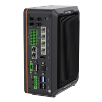
- LAN ports
- 5+ LAN ports
- USB 3 ports
- 2 USB 3 ports
- Light outputs
- 4 built-in channels
- Memory
- 16 GB
Camera selection belongs to the inspection and tracking requirements. The area scan cameras category and camera finder help narrow that choice. The LS-MV-133GM-GE is a camera candidate to assess against those requirements, not a queue controller.
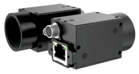
- Sensor format
- 1/2.7"
- Interface
- GigE
- Resolution
- Up to 3 MP
- Shutter
- Global
Keep exposure, trigger timing, target deduplication and tracking validation in the acceptance plan. Replacing the camera will not correct a queue that retains completed picks or a PLC that accepts stale counts. Use the camera configuration starting point only after defining the imaging task and supported acquisition interface.
Commission against throughput and missed picks
Commission in stages under the machine's approved procedures. Log queue counts, status age, requested speed, actual speed, successful picks and expired targets on a common timeline.
- Observe without feedback. Establish queue behavior at fixed validated speeds and representative loading conditions.
- Measure the control direction. Confirm that increasing speed produces the expected change in usable arrivals after the measured delay.
- Enable bounded regulation. Start with conservative speed differences, hysteresis and acceleration limits.
- Exercise disturbances. Test sparse loading, dense loading, a temporarily unavailable picker and changing pick cycle times.
- Verify fault handling. Test stale status and restart recovery using approved simulation or commissioning methods, without defeating protective functions.
- Compare production outcomes. Accept the strategy only if successful throughput improves or remains adequate without unacceptable missed targets or queue oscillation.
Continuous motion is not always the right answer. If the slowest acceptable speed still supplies more targets than the robots can pick, the queue will eventually overflow. Reduce upstream release, add validated accumulation capacity, increase picking capacity or use controlled stops where the process permits them.
Likewise, a sparse queue caused by detection failures should trigger an imaging investigation, not a faster belt. If higher speed shortens the picking window enough to increase misses, regulate target age or remaining travel alongside occupancy.
Before ordering or programming, prepare the queue definition, measured delay, speed envelope, communications interface and fallback behavior. Bring those details to applications support to review the vision components without assuming they provide the complete conveyor-control solution.
Questions
Can the latest camera object count control conveyor speed?
No. Image detections can include repeated observations, rejected parts and objects that are no longer available for picking. Speed regulation needs a defined count of distinct eligible targets. Track reservations, completed picks and expired targets separately so the PLC knows what the occupancy measurement represents.
How often should the PLC receive queue status?
Choose the interval from buffer consumption time, transport delay and measured communication performance. Faster updates are useful only when the measurements remain coherent and the controller respects process delay. Include a sequence counter and a timeout so an old measurement cannot masquerade as current status.
Will reducing conveyor speed always reduce queue occupancy?
Not necessarily. Slowing can reduce replenishment while also increasing the time existing targets remain reachable. The resulting count depends on arrivals, successful picks and expirations. Measure these separately at fixed speeds before choosing the feedback direction or interpreting a falling queue as improved performance.
What should happen when queue communication stops?
Leave ordinary queue regulation and use the fallback established for the machine's process and risk assessment. This may involve a bounded hold, reduced speed or controlled stop. Do not interpret missing data as an empty queue, and require fresh valid status before returning to automatic regulation.
Does this strategy require a new vision controller?
A dedicated controller is not automatically required. The installed system must expose reliable queue information and support a documented, non-blocking route to the PLC. Verify software compatibility, communication timing and responsibility for speed commands before deciding whether additional vision hardware is necessary.