
Sharing a conveyor encoder does not automatically share a robot's conveyor-tracking function. One belt can have one physical encoder while several robots need separate tracking contexts, position references, or interface resources. For a cell with shared pick and place conveyors, start by mapping which robot follows which belt. Then check the documented controller architecture and electrical interface. This separates the hardware you actually need from connector counts that reveal little about tracking capacity.
Start with the robot-by-conveyor matrix
Draw the conveyors as independent motion sources, not simply as sections of the same production line. A pick belt and a place belt normally require separate position measurements when their motion can differ. Equal commanded speeds do not prove equal displacement: acceleration, stops, and mechanical slip can separate their actual positions.
For two robots that both pick from one moving conveyor and place onto another, the tracking matrix is:
| Tracking consumer | Pick conveyor | Place conveyor |
|---|---|---|
| Robot A | Required | Required |
| Robot B | Required | Required |
This arrangement has two measured conveyor motions and four robot-to-conveyor tracking associations. It does not, by itself, specify the number of interface modules.
Add the camera as another position-dependent consumer. Its job is to associate each detected object's location with the correct conveyor position. That association is separate from deciding which robot owns the object and which controller updates its moving coordinates.
If a robot places onto a stationary fixture rather than a moving belt, remove that tracking requirement from the matrix. Count actual motion-following tasks, not every conveyor visible in the cell.
Separate encoders, channels, and tracking ownership
Use distinct names for the resources being counted:
- Physical encoder: the device measuring conveyor displacement.
- Encoder input channel: hardware that receives and counts an encoder signal.
- Tracking context: the software state that relates conveyor position to a moving coordinate system or object queue.
- Tracking owner: the controller or motion task responsible for maintaining and consuming that state.
- Interface module: the hardware package containing whatever input and tracking resources its documentation specifies.
The required association count follows directly from the matrix:
For the example, the arithmetic is 2 robots × 2 conveyors = 4 associations. Extending the same arrangement to six robots produces 6 × 2 = 12 associations, not necessarily twelve modules.
Hardware counts depend on how the documented architecture implements those associations:
| Documented architecture | Consequence for the example |
|---|---|
| Each robot-conveyor association requires a dedicated single-channel module | Four modules are required |
| Each robot can use one module containing two independent conveyor channels | Two modules can cover the four associations |
| A shared controller distributes conveyor state to multiple robot tasks | Count its permitted simultaneous tracking contexts and ownership rules |
| A second connector selects an alternative encoder for the same tracking context | The connector does not add another independently tracked conveyor |
These are conditional examples, not interchangeable wiring options. Shared physical hardware may still contain robot-specific resources that cannot be pooled.
Read interface capacity, not connector labels
A connector count is not a conveyor-capacity specification. Before ordering, find explicit answers in the manufacturer's documentation for the exact hardware revision and installed software release.
Check these points separately:
- How many encoder inputs can count simultaneously?
- How many independent conveyor coordinate systems can run simultaneously?
- Which robot tasks may consume each conveyor state?
- Can several robots track the same conveyor concurrently?
- Is an additional input independent, selectable, redundant, or reserved?
- Does the required function need an option or licensed software feature?
Quadrature labels also cause confusion. The A and B signals are phase-related components of one encoder measurement. On a differential interface, A+ and A− form one signal pair; B+ and B− form another. Neither naming pattern proves that two encoders are supported.
If documentation remains ambiguous, request a written topology confirmation from the manufacturer or its authorized distributor. Include the tracking matrix, controller arrangement, and required simultaneous operations rather than asking only how many encoders fit.
Distribute signals only through compatible interfaces
Sharing one physical encoder between several receivers can be possible, but passive branching is not a universal solution. Compatibility depends on the encoder output circuit, receiver inputs, cable arrangement, and termination requirements.
Check the complete signal path:
- Output type and voltage range, including differential or single-ended signaling.
- Receiver thresholds, input loading, and isolation arrangement.
- Maximum permitted count rate and its definition.
- Termination locations and permitted receiver loading.
- Cable length, branching restrictions, shielding, and grounding instructions.
- Index or reference signals required by each consumer.
- Behavior when one receiver loses power or disconnects.
Do not assume that a signal named A or B has the correct electrical characteristics for every receiver. Likewise, an encoder powered from one controller must not acquire an unintended second supply through another connection.
Where the documented loading or cable topology does not permit direct distribution, use a compatible encoder distribution interface. Check whether it preserves direction, reference pulses, and the required timing relationship across outputs.
Select camera and I/O cables by the documented interface and pinout, not connector appearance. The accessories finder helps locate cable types after those requirements are known.
Camera data, power and I/O cables
366 models · from $39.00Encoder feedback used for conveyor tracking is not automatically suitable for a safety function. Keep safety-related feedback within the machine's validated safety architecture.
Calculate count rate and position sensitivity
Specify resolution as decoded counts per unit of conveyor travel. Encoder cycles, pulses, and decoded counts can mean different things in different data sheets, especially when quadrature decoding counts multiple edges.
For a measured conveyor movement:
Suppose a commissioning measurement records 4,000 decoded counts over 100 mm of belt travel:
- Counts per millimeter = 4,000 / 100 = 40 counts/mm.
- Distance per count = 1 / 40 = 0.025 mm/count.
- At 600 mm/s, the required count rate is 600 × 40 = 24,000 counts/s.
If the selected decoding mode counts four edges per quadrature cycle, that example represents 24,000 / 4 = 6,000 cycles/s. Compare the correct quantity with the interface limit: a specification stated in cycles per second cannot be compared directly with decoded counts per second.
Timing can dominate the result. At the same belt speed, 1 ms of timing uncertainty corresponds to 600 × 0.001 = 0.6 mm of position uncertainty. Fine encoder resolution therefore does not compensate for an uncertain image-to-position association.
These calculations estimate digital resolution and timing sensitivity, not total positioning accuracy. Wheel slip, mechanical compliance, calibration, and robot tracking performance remain separate contributors. Check the maximum count rate at peak operating speed, including documented overspeed conditions.
Keep image position and conveyor position connected
A camera detection needs a conveyor-position reference corresponding to the relevant exposure event. The time at which an application receives the image is not necessarily that event.
Depending on the documented architecture, the association may use a latched encoder count, a hardware event, or synchronized timestamps. Verify which mechanism the system actually implements and where any fixed offset is applied.
For acquisition-side timing, use the guide to camera triggering with external pulses. For object age, queue handling, and delayed results, see conveyor scene timing and stale pick data. Those checks complement channel planning; they do not establish how many tracking interfaces a controller supports.
Store enough information to trace an object through the cell: its identifier, source conveyor, captured position reference, calibration revision, and assigned tracking owner. A shared encoder does not prevent two robots from attempting the same object unless the application also manages ownership.
Restart behavior matters as well. Follow the principles in conveyor vision startup synchronization when restoring queues and references. An encoder count that resets while an old object queue survives can create plausible but incorrect coordinates.
Choose vision hardware without confusing its role
Separate the vision-processing equipment from the robot's documented conveyor-tracking interface. A vision controller may acquire images, run inspection logic, and exchange results without implementing the motion controller's required encoder function.
The MV-VC2101-128G40-NN vision controller illustrates why configuration details matter. Its catalog description identifies the basic version as lacking I/O and lighting functions. Do not infer encoder acquisition or robot tracking support from the presence of network and USB connections.
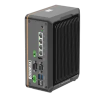
- LAN ports
- 3-4 LAN ports
- USB 3 ports
- 2 USB 3 ports
- Memory
- 16 GB
- Processor
- Intel N-series
The LS-MV-133GM-GE area scan camera is a catalog example of a monochrome GigE camera with a global shutter. That identifies its imaging role, not its compatibility with a particular tracking application, trigger circuit, or software interface.
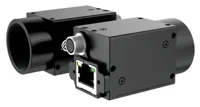
- Sensor format
- 1/2.7"
- Interface
- GigE
- Resolution
- Up to 3 MP
- Shutter
- Global
Use the area scan cameras category and camera finder to narrow imaging requirements. Review vision controllers separately for processing and connectivity requirements. Confirm software support, trigger behavior, and result-transfer requirements before treating either example as a system selection.
Neither product is presented here as an encoder distributor or as a replacement for a robot tracking module.
Verify the topology before production motion
Begin with a documented signal test under the machine's approved commissioning procedure. Secure the machine against unexpected motion whenever wiring or mechanical work is required. Dynamic tests must preserve guarding and safety functions.
Record each receiver's count while the conveyor moves through a measured distance. Check both supported directions and confirm that the configured scale and sign produce consistent physical displacement.
Then test the complete association chain:
- Confirm each encoder feeds only its intended conveyor contexts.
- Compare receiver count changes during the same measured movement.
- Verify each robot task can use every association marked in the matrix.
- Trigger an image and trace its position reference into the object queue.
- Test simultaneous operation, not just one robot at a time.
- Exercise documented stop, restart, communication-loss, and reference-recovery behavior.
Absolute count values need not match if receivers use different documented offsets or reset histories. Compare displacement and reference relationships, not raw totals alone.
If counts diverge, investigate signal integrity, loading, scaling, and decoding before adjusting camera calibration. If counts agree but targets drift with speed, investigate timing and tracking transformations. If the fault appears only after restart, examine reference restoration and queue invalidation.
Order against a verified allocation checklist
The usual shared-encoder arrangement is wrong when the measurement no longer represents the motion being tracked. Independently driven belts need independent position references. A slipping measuring wheel, an accumulating conveyor, or objects moving relative to the belt may require a different measurement strategy.
More encoder receivers also cannot solve a controller ownership restriction. If simultaneous tracking is unsupported, the legitimate options are a documented architecture change, supported controller configuration, or revised process sequence.
Before releasing the parts list, confirm:
- Motion sources: every independently moving conveyor has an appropriate position measurement.
- Tracking matrix: every robot-conveyor association has an allocated, supported context.
- Capacity evidence: the exact hardware and software documentation supports simultaneous operation.
- Electrical design: receiver loading, distribution, termination, power, and cable topology are approved.
- Count budget: decoding mode, peak rate, direction, and scaling are recorded.
- Image association: each detection carries the correct conveyor-position reference.
- Recovery behavior: stops, resets, and stale objects have defined handling.
- Purchasing scope: cameras, vision controllers, tracking interfaces, distribution hardware, and cables have separate roles.
Bring this matrix and interface checklist to application support before ordering the vision components. Once imaging requirements are established, use the camera configurator to organize that part of the system.
The configurator matches a camera, lens, light, light controller and cables to each other, step by step, and lists only parts that fit what you already picked.
Questions
Do two robots tracking two conveyors always need four boards?
No universal board count follows from that arrangement. It creates four robot-to-conveyor tracking associations, but the required hardware depends on independent channel capacity, permitted sharing, and controller ownership. Confirm those capabilities for the exact hardware revision and software configuration before converting associations into a module quantity.
Can one conveyor encoder connect directly to several receivers?
Only when the encoder and receiver documentation permits the resulting electrical load and wiring topology. Check signaling type, termination, grounding, cable length, and behavior when a receiver loses power. If direct branching is unsupported, specify a compatible distribution interface rather than improvising a splitter.
Does a second encoder connector mean a second conveyor channel?
Not necessarily. An additional connector may provide an alternative source, redundancy, or another function within one tracking context. Look for an explicit statement about independent simultaneous counting and conveyor tracking. Connector labels and the number of terminals are not sufficient evidence of capacity.
Can a vision controller replace the robot's conveyor-tracking interface?
Only if the documented system architecture explicitly assigns that function to it. Image processing, network connectivity, encoder counting, and robot motion tracking are separate capabilities. Verify the required interfaces and supported software integration instead of assuming that a vision-processing device can replace motion-specific hardware.