
Red and yellow parts may look different to you yet produce nearly identical values in a monochrome image. The reverse can also happen: suitable illumination can make those materials easy to separate without measuring full color. For a sorting station that moves between production and exhibition environments, the decision depends on measured separation and ambient-light control. You will need a repeatable image recipe, representative samples, and an explicit response when the image cannot support a confident classification.
Decide from material response, not the color name
A monochrome camera measures brightness weighted by its spectral sensitivity. It does not report whether an object is red or yellow. A threshold can classify those materials only when their recorded brightness distributions remain sufficiently different throughout the operating conditions.
The visible appearance is not enough to predict the result. Many red and yellow materials both reflect red light strongly, so red illumination may make them look similar. Green illumination can sometimes increase their difference because a yellow material may reflect wavelengths that a red material absorbs. Pigments, coatings, gloss, and the camera response determine whether that actually happens.
Use monochrome classification when the task involves a fixed set of materials and testing demonstrates a reliable brightness gap. Choose color acquisition when you need more information than a single brightness measurement can provide. Neither option removes the need for controlled lighting.
For conveyor applications, keep this decision separate from image timing and motion. The conveyor camera selection guide addresses those constraints; here, the acceptance criterion is material classification.
Understand what changes the grayscale value
A simplified model explains why changing the light can change the classification. For a linear, unsaturated monochrome measurement at fixed gain:
This is an explanatory model, not a calibration equation. It assumes fixed viewing geometry and omits the directional behavior of glossy surfaces. Processed image formats may also introduce gamma, tone curves, or other nonlinear changes.
The useful distinction comes from differences in reflectance weighted by the light spectrum and camera sensitivity. Changing exposure scales both populations; it cannot create spectral information that the image does not contain.
Ambient light contributes to the same measurement as your inspection light. Choosing a lamp with a different apparent color from the room lighting does not isolate the camera from that room lighting.
If the camera exposes through changing ambient illumination, the measured values can drift even though the inspection light remains constant. Automatic exposure or gain can further move both populations, invalidating a threshold established earlier.
Compare illumination with a controlled test
Start with the actual red and yellow materials, including different production batches and surface finishes. Keep camera position, lens aperture, exposure, gain, background, and measurement region unchanged while comparing illumination.
| Illumination approach | What to investigate | Main limitation |
|---|---|---|
| White light | Whether the populations already differ in brightness | Brightness mixes a broad range of wavelengths |
| Red light | Whether the actual materials reflect red differently | Red and yellow materials may both appear bright |
| Green light | Whether the yellow material stays bright while the red material darkens | Pigment and coating differences can reverse expectations |
| Other selected wavelengths | Whether an observed reflectance difference provides greater separation | Visible color names do not predict the result |
Do not choose infrared merely because ambient lighting looks white. It measures reflectance outside the visible color judgment, so visibly different parts may become indistinguishable.
Explore ring lights when illumination around the lens suits the part geometry. Use bar lights when independently adjusting lighting direction helps control glare. The lighting finder supports comparing the available light types and colors.
The LS-LRDS-96-0-R is a red ring-light candidate for a material-response trial. Its color is not evidence that it will distinguish the parts.
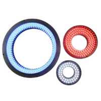
- Size
- 50-100 mm
- Type
- Diffused
- Angle
- Low angle (0-15°)
- Voltage
- 24 V
The LS-LLDS-372-28-W provides a white bar-light alternative. Evaluate its coverage and reflection pattern on the proposed fixture before choosing it.
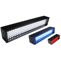
- Size
- 200-400 mm
- Type
- Diffused
- Voltage
- 24 V
Where curved or glossy surfaces dominate the image, changing geometry may matter more than changing wavelength. The guide to diffuse dome illumination explains that alternative and its limits.
Measure populations rather than one good image
Locate each part first, then measure an interior region that excludes the background, rim, shadows, and obvious highlights. A mean or median intensity can be useful, but verify that the chosen statistic remains stable across the surface variations you expect.
A practical screening test might include 30 physical samples per class, multiple orientations, and several positions across the field. Treat those numbers as a starting experiment, not a reliability claim. Repeated images of the same few parts do not replace independent material samples.
Record the sample identity, image settings, illumination condition, position, and measured statistic. Use separate development and validation samples so that threshold tuning does not consume all available evidence.
Sampling also matters. Suppose the field width is 120 mm and you need 10 pixels across a 2 mm measurement patch:
This estimates spatial sampling only. It does not establish classification accuracy, optical sharpness, or the required number of independent samples. Use the camera resolution calculator to check another field width or measurement region.
Before collecting the dataset, turn off automatic exposure and gain using the camera's documented controls. Confirm that the stored settings match the acquired frames; the per-frame metadata verification guide explains how to investigate that relationship.
Build a threshold with a rejection region
Consider an illustrative test using an 8-bit image, where digital values range from 0 to 255. After measuring the interior-region median, the observed red population spans 55–80 and the yellow population spans 135–165.
A single threshold would separate this development dataset. However, the observed extrema are not guaranteed limits for future production. Unseen materials, pose changes, and ambient conditions may reduce the gap.
A more conservative decision can include an indeterminate band:
- Classify as red when the statistic is at or below 90.
- Classify as yellow when the statistic is at or above 125.
- Route values between those boundaries to an inspection-failed or unknown state.
Those illustrative boundaries leave 10 digital counts between each observed population and its nearest rejection boundary. They are not universal settings. Determine acceptable margins from validation data and the consequences of an incorrect sort.
Report false-red decisions, false-yellow decisions, and unknown results separately. Also report missed detections, because a classifier can appear accurate when difficult parts never reach it.
Control ambient light before compensating in software
A light-colored inspection lamp cannot prevent ambient light from reaching the sensor. First reduce unwanted illumination with an opaque hood, baffles, controlled openings, and a stable background. Keep these additions clear of machine motion and preserve access to required guards and safety functions.
Measure ambient influence using matched images with the inspection light on and off. Hold exposure, gain, and geometry fixed. The off image reveals background illumination, while the difference estimates the controlled-light contribution when the response is linear and neither image is clipped.
For example, suppose a measurement contains 140 counts from controlled illumination and 20 counts from ambient light, after black-offset correction. Its total is 160 counts. If the ambient contribution rises to 40 counts:
That shift can consume a useful threshold margin. Different materials may shift by different amounts because the ambient spectrum also matters.
A lens filter matched to selected illumination can reduce out-of-band ambient light. It cannot reject ambient light within its passband. Check transmission, viewing-angle effects, camera sensitivity, and the available signal before treating filtering as the solution.
Synchronized pulsed lighting can increase the controlled-to-ambient contribution during exposure, within the documented limits of the light and controller. For timing considerations, consult the external-trigger frame-rate guide. Verify the result with images rather than assuming synchronization removes ambient effects.
Know when a color camera is the better choice
Move to color acquisition when no tested illumination produces stable monochrome separation, when additional materials must be identified, or when intensity differences are too sensitive to finish and orientation. Color measurements provide multiple channel responses instead of one weighted brightness value.
Under controlled white illumination, channel ratios or normalized chromaticity can reduce sensitivity to some overall brightness changes. They do not make the system independent of illumination spectrum, clipping, shadows, or specular reflections. Lock exposure, gain, white balance, and relevant processing during validation.
The LS-MV-133GM-GE is a monochrome GigE candidate. The MV-CU020-90GC is a color GigE candidate. These represent different acquisition choices, not a guarantee of separation for your materials.
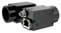
- Sensor format
- 1/2.7"
- Interface
- GigE
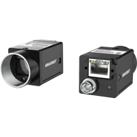
- Sensor format
- 1/1.7"
- Interface
- GigE
Compare area scan cameras using the camera finder, then verify compatibility with your acquisition software. A network interface does not establish which image-processing functions the application supports. The GigE Vision compatibility guide covers that separate check.
Validate the complete operating envelope
Challenge the selected recipe under the conditions that could move either population toward the decision boundary. Include room lights on and off, nearby displays, different ambient directions, expected daylight exposure, and the intended exhibition setup.
Test the corners and center of the field, minimum and maximum part heights, rotation, normal contamination, and representative finish variation. Repeat after the equipment has reached operating temperature and after restarting the acquisition system.
Keep the recipe fixed during these tests. If you retune it for each environment, you have demonstrated several recipes rather than one transferable configuration. Where different recipes are acceptable, define how they are selected and verified.
Preserve labeled validation images, including failed detections and unknown decisions. Inspect errors by material batch and lighting condition rather than relying only on an aggregate accuracy percentage. A system that fails consistently on one finish needs a design change, not merely more average-case images.
A small test with no observed errors cannot establish an extremely low field failure rate. Set the required validation scope from production risk and maintain a documented route for ambiguous parts.
Check these details before ordering
Use the following checklist to turn the experiment into a purchase specification:
- Define the material classes and allowed surface variation; color names alone are insufficient.
- Record the smallest usable measurement region, field width, and required sampling.
- Preserve the illumination geometry that produced the best separation.
- Specify ambient shielding and verify access, cleaning, and machine clearances.
- Check lens-filter fit, spectral transmission, and remaining exposure margin if filtering is proposed.
- Verify acquisition compatibility and that required inspection functions are properly licensed.
- Confirm the application can return unknown, missed-part, and acquisition-fault states separately.
- Save camera settings, processing parameters, reference images, and validation results together.
Do not force a monochrome solution when its measured populations overlap. Equally, do not replace the camera before testing whether stable illumination solves the problem.
Start a camera configuration once sampling and interface requirements are defined, or a lighting configuration once the material trials identify a useful geometry and spectrum. If separation remains uncertain, use application support with representative images, measured distributions, and the tested lighting conditions.
Questions
Can a monochrome camera distinguish red and yellow parts?
Yes, if the actual materials produce consistently different grayscale measurements under the selected illumination. The camera is separating brightness responses rather than measuring color directly. Validate multiple material batches, finishes, positions, and ambient conditions before using a fixed threshold for production.
Which light color should be tested for red and yellow sorting?
Red lighting is not automatically the right choice because many red and yellow materials both reflect it strongly. Green illumination may produce a greater difference, but the result depends on the pigments, coatings, and camera sensitivity. Compare candidate light colors on representative parts with fixed image settings.
Will a matching lens filter eliminate ambient-light problems?
It can reduce ambient wavelengths outside its passband, but ambient energy inside that passband still reaches the sensor. Physical shielding and controlled illumination remain useful. Validate the filter with the intended camera and lens, including signal loss, reflections, and the worst expected ambient conditions.
When should a color camera replace a monochrome camera?
Use color acquisition when brightness distributions overlap despite suitable lighting, when additional material classes must be identified, or when surface variation makes monochrome decisions unstable. A color camera still needs controlled illumination and fixed processing settings; extra channels do not automatically provide lighting-independent classification.
What should happen when a part falls between the class thresholds?
Return an explicit unknown or inspection-failed result and route the part according to the machine's validated handling logic. Do not silently force the nearest class. Track unknown rates alongside incorrect classifications, and retain images so that lighting drift or new material variation can be investigated.