
Shiny parts are hard to light because they behave like mirrors. A foil lid, a chrome-plated fitting or a curved can end shows the camera a reflection of whatever surrounds it, so every LED, edge and gap in the light shows up as a glint. A dome light fixes that by surrounding the part with one even, glowing surface. This guide is for engineers who must inspect print, dents or contamination on reflective, curved or wrinkled parts. You will learn the two angles that decide whether a dome works, how large it must be, how to handle the dark spot from the camera hole, and when a different light is the better tool.
Why shiny and curved parts need a dome
A matte surface scatters light in all directions, so almost any light gives a usable image. A shiny surface reflects each ray at one angle only. The camera sees a bright spot where a ray from the light bounces straight into the lens, and darkness everywhere else. On a flat mirror that is one spot. On a curved or wrinkled surface it is dozens of streaks and points, and they move as the part moves.
The cure is to make every direction look the same. If the part sits under an evenly lit hemisphere, each point on the surface reflects some part of that hemisphere into the lens, and all of it has the same brightness. Engineers call this cloudy-day illumination: on an overcast day a polished car shows no sharp highlights because the whole sky is one soft source.
A dome light builds that sky in a box. LEDs around the rim shine up into a white, diffusing inner surface, which then lights the part from nearly every angle. The camera looks down through a hole in the top. What reaches the image is the shape of the print, a dent or a stain, not the reflection of the light. Browse the dome lights to see the range of sizes and colours.
The two angles that decide whether a dome works
Two pieces of geometry explain almost every dome success and failure. Both are easy to estimate with a ruler and a protractor.
The first is the reflection rule. When a mirror-like surface tilts by an angle θ, the reflected ray tilts by twice that angle. A wrinkle sloped at 20° therefore sends the camera's line of sight off at 40° from vertical, and the light must be there to fill it.
The second is the coverage angle. A part sitting a gap WD below the dome's opening only sees the dome within a cone set by that opening. For a point a distance x from the centre, on the side nearest the rim:
Here a is half the opening (or half the emitting diameter) and WD is the gap from the dome's lower edge to the part. The point images evenly only if the coverage angle is larger than the reflected angle. Treat this as an estimate: real domes are not perfect hemispheres, and the brightness near the rim is often a little uneven.
Two rules of thumb follow. Steep slopes need the part close to the dome, because the cone narrows quickly as WD grows. And the opening must extend well past the part's edge, because the edge points are the ones that run out of dome first.
The camera hole and the dark spot
The hole that lets the camera see the part is the one place in the dome that does not glow. On a flat, mirror-like area facing the camera, the lens sees the hole reflected straight back, and the image shows a dark circle. This is the classic dome failure on flat foil, polished discs and glossy labels.
You can predict the size of that spot. Let D be the distance from the part up to the hole and H the distance from the part up to the lens. On a flat mirror the camera sees the hole's reflection as if it sat a distance D below the surface, so:
The second line says which surfaces escape the spot: any area tilted by more than that slope reflects the glowing dome rather than the hole. Wrinkled foil therefore often shows a patchwork of bright folds and dark flat patches in the centre of the field.
The hole also limits what the camera can see. If the lens sits a distance L above the hole, the field visible through it is about hole diameter × H / L wide. Mount the lens close to the hole and the field grows; lift it away and the hole starts to crop the image like a keyhole.
A worked example: print on a wrinkled foil lid
You need to read a printed date on the foil lid of a round tub. The lid is 50 mm across, and the foil wrinkles with slopes of up to 20°. The candidate light has a 116 mm emitting diameter and a 35 mm camera hole:
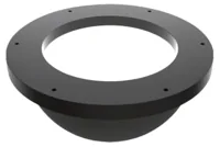
- Size
- 100-200 mm
- Voltage
- 24 V
- Reflected angle at the steepest wrinkle: 2 × 20° = 40°, and tan 40° = 0.84.
- The edge of the lid is at x = 25 mm, and half the emitting diameter is a = 58 mm, so the dome extends 33 mm past the edge.
- Largest gap that still covers 40° at the edge: 33 / 0.84 = 39 mm. Set the lid 20 mm below the dome for margin. The coverage angle at the edge is then atan(33 / 20) = 59°, which handles slopes up to about 29°.
- Distance from the lid to the hole: about 20 mm of gap plus roughly 58 mm of inner dome height, so D ≈ 78 mm. That inner height is an estimate for a near-hemispherical dome; measure your own.
- Slopes that escape the hole: ½ × atan(17.5 / 78) = ½ × 12.6° ≈ 6°. Flat areas of foil flatter than about 6° will look dark.
- With the lens 100 mm above the hole, H = 178 mm. The dark spot is about 35 × 178 / 256 = 24 mm across, and the field visible through the hole is about 35 × 178 / 100 = 62 mm wide.
The 62 mm field covers the 50 mm lid with 6 mm of margin each side, and the 33 mm overlap past the edge handles the steep wrinkles. The weak point is the 24 mm dark spot in the middle of a flat, 50 mm lid. Two fixes work. Print the date away from the centre, or tilt the lid holder by about 8°, so the flat centre reflects the dome instead of the hole. If neither is possible, change the light type, as the next section explains.
With the distances known, the focal length guide gives the lens. Here a field of about 62 mm at 178 mm calls for a lens of about 21 mm on a camera with an 8.45 mm wide sensor. The nearest standard steps are 16 and 25 mm. The 25 mm lens sees about 52 mm, just wider than the lid; the 16 mm lens sees about 86 mm, and the hole would crop that view to a circle. Take the 25 mm lens and confirm that the lid's position play fits inside the view.
Dome, flat dome or arch: choosing the type
Dome lights come in several shapes. They differ in how much of the sky they cover, how much height they need and whether they leave a hole.
Classic hemispherical domes
The tall, round dome gives the widest coverage and suits the steepest curves: bottle caps, can ends, ball bearings and curved metal fittings. The trade-off is height. A typical dome is about half as tall as it is wide, plus the gap below it, which matters on a crowded machine. Compare the hole size as well as the emitting diameter. A smaller hole gives a smaller dark spot but leaves less room for the lens.
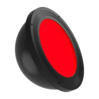
- Size
- 100-200 mm
- Voltage
- 24 V
- Size
- 100-200 mm
- Voltage
- 24 V
Flat dome lights
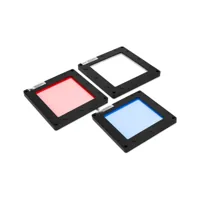
A flat dome is a thin panel that lights the part through a diffusing light-guide plate. The two below are only 11 and 11.5 mm thick. In the usual design the camera looks through the panel itself, which still glows where the lens looks through it, so a flat mirror-like area does not show a dark hole. That makes flat domes a good match for glossy packaging film, foil bags and flat-ish cans. Check the product drawing for the viewing area before you plan the lens.
The catch is coverage. A flat panel only reaches the angles its edges subtend, so the same coverage formula applies with a set to half the panel width. Keep the panel close to the part, typically closer than for a hemispherical dome, and use it where slopes stay moderate.
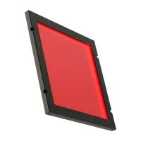
- Size
- 100-200 mm
- Voltage
- 24 V
- Size
- 100-200 mm
- Voltage
- 24 V
The shadowless lights category holds more flat and low-profile designs of this kind.
Arch lights for long, round parts
A cylinder lying along a line needs dome-like light around its circumference but not along its length. An arch light is a half-cylinder of diffuse light, open at both ends, that you lay along the part. It suits battery cells, shafts, tubes and other long round parts where a round dome would be too small or too tall. The arch light is one example; check that its length covers the inspected section with margin at both ends, because the ends see less of the arch.
Colour, power and speed
Pick the LED colour for contrast, not for looks. A coloured feature reflects its own colour, so it looks bright under light of that colour and dark under the opposite colour. Blue or green light makes red print dark on silver foil; red light would make the same print nearly vanish. With a monochrome camera, test all three colours on a real part before you order. Most domes in the range come in red, green, blue and white.
Diffusing surfaces lose light, so a dome usually needs more power than a direct ring light for the same exposure. That matters on a moving line. Motion blur equals speed × exposure: a part moving at 500 mm/s smears 0.5 mm during a 1 ms exposure. If each pixel covers 0.05 mm of the part, that is a 10-pixel smear. To hold the blur near one pixel, the exposure must drop to about 0.1 ms, which means about ten times more light.
A controller that strobes the light in step with the camera exposure is the usual answer. Short pulses at higher current deliver the light only when the shutter is open. See the light controllers for strobe and analog models that match the power of your dome.
Checks on the bench
Before you commit to a light, run these tests with real parts, not a clean sample from the drawing office:
- Worst-case slope. Put the most wrinkled or most curved part under the dome. Any streaks near the edges mean the gap is too large or the dome too small.
- Dark spot. Image the flattest part. If the spot covers a feature, tilt the part, move the lens closer to the hole or switch to a flat dome.
- Edge uniformity. Move the part to the edges of its position tolerance. The grey level should stay even enough that one threshold still separates good parts from bad at both edges.
- Ambient light. A dome is open at the bottom. Turn the room lights on and off; if the image changes, add a shroud or raise the dome's brightness against a shorter exposure.
- Heat and space. Check the mounting height, the cable route and the operating temperature range on the product page against your machine.
When a dome is the wrong light
A dome erases surface texture on purpose. That is a problem when the texture is the defect you need to see:
- Shallow scratches, embossing and engraving. These show best with low-angle light that casts a shadow or a glint off the edges. A dome flattens them out (see the figure below).
- Truly flat mirror-like parts. Wafers, glass and polished flat metal image more evenly under a coaxial light, which lights from the camera's own direction and has no hole.
- Outlines and holes. For edge measurement and presence checks on opaque parts, a backlight gives a sharper silhouette than any front light.
- Parts too large for a dome. Above a few hundred millimetres, domes become heavy and expensive. Large-format domes exist, but a pair of diffuse bar lights or an arch often costs less for a long part.
If the part is shiny but you are not sure which of these applies, start with the lighting selection guide, or filter every light by type, size and colour in the light finder.
The configurator matches a camera, lens, light, light controller and cables to each other, step by step, and lists only parts that fit what you already picked.
Next step
Measure three numbers before you choose: the part width, the steepest slope on its surface and the gap you can allow between the part and the light. Those give the dome size from the coverage rule, and the hole and lens distances give the dark spot and the visible field. If the numbers are tight, send us the part and the distances and we will check the light and lens choice with you. Expert support is free with every order.
Questions
How large should a dome light be for my part?
Start from the part width and add twice the gap times the tangent of twice the steepest surface slope. For a 50 mm part with 20 degree slopes, 20 mm below the dome, that gives an opening of about 84 mm. Then add margin for part position, and choose the next size up.
Why is there a dark circle in the middle of my image?
The camera sees its own viewing hole reflected in the flat, shiny centre of the part. A smaller hole, a lens closer to the hole or a flat dome light shrinks or removes it. Tilting the part a few degrees also moves the reflection out of the area you inspect.
Can a dome light freeze a fast-moving part?
Yes, if the light is bright enough for a short exposure. Diffusers lose light, so drive the dome from a controller that can strobe it in step with the camera exposure, and keep the motion blur under about one pixel.
Should I use a dome light or a coaxial light on a flat, polished part?
On a truly flat mirror-like part, a coaxial light usually gives the more uniform image, because it lights the part from the camera's own direction and leaves no hole. A dome is the better choice as soon as the surface curves, dents or wrinkles.
What colour should the dome light be?
Choose the colour for contrast. A coloured feature looks bright under light of its own colour and dark under light of the opposite colour, so try the print or defect under red, green and blue before you order. White is the safe choice for a colour camera.