
A moving web does not pause at an acquisition frame boundary. A label, scratch, or component can therefore appear partly at the bottom of one image and partly at the top of the next. For inspection applications receiving continuous line-scan data, overlapping images provide a practical way to preserve complete objects. You can assemble those images in application memory without depending on a driver-specific overlap feature. The main decisions are how many rows to retain, who owns each buffer, and which image owns each detection.
Separate acquisition chunks from inspection images
Treat the camera stream as an ordered sequence of rows. The acquisition system may deliver those rows in rectangular chunks, but those chunk boundaries do not have to become inspection boundaries.
Keep the trailing rows from the previous chunk and prepend them to the next chunk. The resulting inspection image contains genuine measurements from both sides of the boundary. Nothing is interpolated, and the camera does not need to acquire those rows again.
Define three quantities before implementing the assembly:
- Source height, S: new rows delivered in each acquisition chunk.
- Overlap, O: previously acquired rows repeated in the next inspection image.
- Output height, B: total rows presented to the inspection algorithm.
For the prepend method, output height equals source height plus overlap. Consecutive inspection images advance by the source height, which is their stride.
This approach does not require a frame grabber specifically for overlap. The camera interface may still require acquisition hardware of its own. Your application needs access to ordered image rows and a documented way to retain or copy their data.
Size overlap from object length and encoder pitch
Choose overlap from the largest feature that must remain complete, including the surrounding context your algorithm needs. A fixed percentage of image height is usually a weaker starting point.
For encoder-synchronized acquisition, let pitch mean the actual material travel between acquired rows. Encoder counts alone are not enough if gearing, trigger division, or material slip changes that relationship.
Use this conservative sizing estimate:
Here, R is an upper bound on the required span in sampled rows. The extra row allows for alignment between the object edges and the sampling grid. For a contiguous feature spanning at most R rows, overlap of at least R minus one rows prevents a full-sized feature from falling across both neighboring window boundaries. This assumes stride is positive and acquisition contains no missing rows.
Suppose the longest object measures 24 mm along travel. The detector also needs 3 mm of context at each end, and the encoder pitch is 0.05 mm per line:
The additional overlap gives some allowance for dimensional variation. It does not compensate for an incorrectly calibrated encoder or an object longer than the design limit.
For free-running acquisition, pitch is approximately speed divided by line rate. Size overlap using the smallest expected pitch, because slower material movement puts more rows across the same object.
Distinguish output height from stride
Two common implementations use the same word, overlap, but produce different image dimensions. Record which convention your application uses.
| Assembly convention | Output height | Stride | Practical consequence |
|---|---|---|---|
| Prepend history to each source chunk | S + O | S | Preserves each complete source chunk and creates a taller output |
| Keep inspection height fixed | B | B - O | Requires a continuous buffer that can form windows independently of source chunks |
With a source height of 2048 rows and overlap of 640 rows, the prepend method produces 2688-row inspection images. Each new image advances by 2048 rows.
With a fixed output height of 2048 rows and the same overlap, stride becomes 1408 rows. That creates more inspection images from the same acquired stream.
Neither convention increases the camera's line rate. Both increase the amount of image content processed because some rows appear in multiple inspection images.
Do not confuse overlap with binning, exposure overlap, or repeated camera triggering. Those change acquisition behavior rather than the arrangement of already acquired rows.
Assemble images with explicit startup and gap handling
Maintain an owned history buffer, an absolute row counter, and an acquisition continuity flag. For the prepend convention, a straightforward sequence is:
- Receive a source chunk and verify its status, dimensions, pixel format, and available sequence metadata.
- Detect any missing chunks or reported transport errors before joining rows.
- Copy the valid source rows into application-owned storage, or retain the acquisition buffer through its documented ownership mechanism.
- Allocate an output buffer and copy valid history rows first, followed by the new source rows.
- Attach the output's absolute starting row and valid-row count as metadata.
- Update history from the newest trailing rows of the assembled valid data.
- Publish the output only after all writes finish, then release acquisition buffers when no longer referenced.
Updating history from the combined valid data also supports overlap larger than a single source chunk. If you instead copy history only from the newest chunk, explicitly restrict overlap to no more than the source height.
For the numerical example, the first acquisition chunk contains absolute rows 0 through 2047. Its trailing history contains rows 1408 through 2047. After receiving the next chunk, the first full overlapped output contains rows 1408 through 4095.
An object occupying rows 1900 through 2300 crosses the original acquisition boundary. It is nevertheless complete in that overlapped output.
Do not invent startup history
At startup, no previous rows exist. Process the first chunk as a shorter valid image with appropriate edge restrictions, or gather enough real rows before producing a full-sized initial window.
If downstream software requires a fixed image shape, a continuous window assembler can collect its first complete window from row zero. It then advances by the chosen stride, independently of acquisition chunk boundaries.
Padding with zeros or copying the first rows into fictitious history can create false edges. Padding is acceptable only when the inspection explicitly masks it as invalid.
After a discontinuity, clear history and repeat startup handling. Joining pre-gap rows to post-gap rows creates an image that never existed physically. Use the camera acquisition failure troubleshooting guide when continuity checks reveal recurring transport problems.
Protect buffer ownership and budget processing load
The most common implementation failure is retaining a pointer after the acquisition system has recycled its buffer. The image may appear correct during light testing, then change while inspection is running.
Prefer a copy-based implementation first. It makes ownership visible and is easier to verify. A zero-copy arrangement is possible only when every referenced source buffer remains valid until all consumers finish.
Check row stride in bytes rather than assuming tightly packed pixels. Padding, packed pixel formats, and multiple channels can make a row occupy more memory than its visible width suggests. Decode or copy according to the documented pixel layout.
For a hypothetical tightly packed image with 2048 pixels per row and one byte per pixel:
That is approximately 5.51 MB per output and 1.31 MB of history, using decimal megabytes. Inspection processes 31.25% more rows than acquisition supplies. Source buffers, queued outputs, algorithm workspaces, and additional copies require more memory.
At 20,000 lines per second, source chunks arrive every 2048 / 20,000 = 0.1024 seconds. A single inspection worker must therefore sustain an average processing time below 102.4 ms per output to avoid an ever-growing queue.
The incoming image payload is 2048 × 20,000 = 40.96 MB/s. Overlapped output content represents 53.76 MB/s. These figures exclude protocol overhead and do not represent total memory-bus traffic.
Give detections global coordinates and a single owner
Overlap solves incomplete images but introduces repeated observations. Convert every detection into a common material coordinate system before counting, measuring spacing, or scheduling downstream actions.
The travel-position formula assumes a known origin and constant distance per acquired row. Preserve encoder positions directly when that assumption does not hold.
Do not simply accept detections whose centers fall in the newly acquired rows. An object centered just before that boundary may be incomplete in the earlier output but complete in the current one.
A safer ownership rule uses an interior acceptance band. For even overlap, place half the overlap above the band and half below it. The band width equals stride, so consecutive bands meet without overlapping.
In the example, reserve 320 rows at each end of each full output. Accept object centers from local row 320 up to, but not including, row 2368. The acceptance band is 2048 rows tall, matching stride.
This works when the object and required context extend no farther than the reserved guard distance on either side of the chosen center. An asymmetric detection anchor needs correspondingly asymmetric guards.
For variable shapes or unstable center estimates, maintain a recent-detection list in global coordinates. Match repeated observations using position, extent, and object identity where available. Choose tolerances below the minimum separation between distinct objects, and test crowded cases.
The camera preview overlay guide is useful for displaying window limits, acceptance bands, and global detection positions during commissioning.
Choose acquisition parts independently of overlap assembly
Start with line scan cameras and the camera finder. Select line length from cross-web sampling, then verify the required line rate, exposure behavior, interface bandwidth, and trigger support in the selected product's documentation.
The LS-MV-LM044M-GE lists a GigE interface and an M42 lens mount.
The LS-MV-L082M20-10GF-V2 lists a 10GigE interface and an M72 lens mount.
These are acquisition candidates, not confirmed matches to the worked example. The supplied catalog information does not establish their supported line rates or application compatibility.
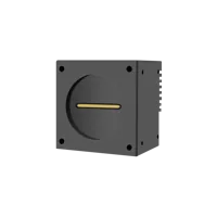
- Sensor format
- APS-C
- Interface
- GigE
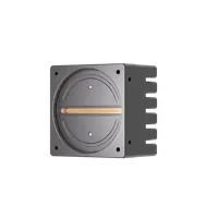
- Interface
- 10GigE
- Lens mount
- M72
Use the GigE Vision software compatibility checks to review software access and transport requirements. The hardware trigger timing guide explains timing checks, although line-trigger limits must come from the selected camera's documentation.
Compare line scan lights through the lighting finder. Evaluate the LS-3LI97522 and LS-2LINS500 against illuminated coverage, mounting space, electrical requirements, and measured contrast on the material.
- Size
- 400 mm +
- Voltage
- 24 V
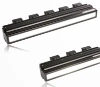
- Size
- 400 mm +
- Voltage
- 24 V
At a travel speed of 1000 mm/s and pitch of 0.05 mm per line, the required line rate is 1000 / 0.05 = 20,000 lines per second. Limiting travel during exposure to half a row pitch gives an exposure ceiling of 0.025 / 1000 = 25 microseconds. This is a motion-blur estimate, not an exposure specification for either light or camera.
For the processing host, evaluate vision controllers against the actual interface, sustained processing load, memory requirements, and software licensing. Camera ports or built-in light outputs do not, by themselves, establish line-scan acquisition compatibility.
The configurator matches a camera, lens, light, light controller and cables to each other, step by step, and lists only parts that fit what you already picked.
Know when overlap is the wrong remedy
Overlap cannot restore lines that were never acquired. It also cannot repair motion blur, insufficient optical resolution, or weak illumination contrast. Fix those problems before increasing buffer sizes.
An object longer than the design limit can still cross every inspection boundary. For continuous defects or unbounded features, carry inspection state across windows instead of expecting every feature to fit inside one image.
Variable material stretch or slip can make fixed row distances unreliable. Validate the relationship between encoder travel and the surface being inspected. Reverse movement also needs explicit handling; a monotonically increasing row counter alone does not describe material position after reversal.
When overlap becomes a large fraction of output height, processing duplication can dominate. Consider longer windows, object-triggered segmentation, or algorithms that retain partial-object state between chunks.
Verify the design before ordering and deployment
Use this acceptance checklist with synthetic row patterns and representative material:
- Row identity: encode a known row index in test images and confirm that repeated rows are identical.
- Boundary coverage: move the longest required object through every possible seam position, including its context margins.
- Startup behavior: confirm that invalid history cannot produce accepted measurements.
- Continuity handling: simulate a missing chunk and verify that history resets rather than bridging the gap.
- Ownership: slow the inspection consumer and confirm that queued images remain unchanged.
- Detection counts: pass closely spaced objects across acceptance-band boundaries and check for missed or repeated results.
- Sustained load: run at maximum intended line rate while monitoring queue depth, processing latency, and memory use.
- Ordering checks: confirm optical coverage, mounting, trigger input requirements, interface hardware, and software access separately from overlap logic.
Start the hardware review with the camera configurator, then use the lighting configurator for the exposure and contrast requirements. If the buffer or timing assumptions remain uncertain, send the row pitch, maximum object length, source height, and pixel format through applications support before choosing parts.
Questions
Does line scan image overlap require a frame grabber?
No special driver overlap feature is required when your application can read ordered rows and manage their lifetime. It can copy retained history ahead of newly acquired data. The camera interface may still require its own acquisition hardware, and the software must expose usable buffers through a documented interface.
How much overlap should inspection images contain?
Base the retained region on the longest object plus the context needed around it, converted into rows using material travel per line. Allow for sampling alignment and dimensional variation. Then verify the result by moving the longest representative object through different positions relative to an inspection boundary.
Does adding overlap increase camera bandwidth?
Repeating rows after acquisition does not increase the camera's incoming payload. It does increase inspection work, output-buffer storage, and usually memory copying. The expansion factor is output height divided by stride, so reducing stride without changing output height can significantly increase processing demand.
What should happen at startup or after missing data?
Only real acquired rows should count as valid image content. You can inspect an initial shorter image with restricted edge acceptance, or wait until enough rows exist for a complete window. After a gap, discard retained history and apply the same initialization policy again.
How do overlapping images avoid counting an object twice?
Translate detections into global row or encoder coordinates before accepting them. Assign each image an interior acceptance band that leaves enough surrounding data for a complete object. Where localization varies between images, add position-based duplicate matching with tolerances that cannot merge neighboring objects.