
A robot can place a screw inside the image without presenting it consistently enough for thread inspection. Small changes in tilt, distance, lighting and residual motion can resemble defects or conceal them. Start with the smallest defect you must detect, then specify sampling, illumination and presentation together. This approach lets you compare cameras against an inspection requirement rather than choosing by megapixels alone.
Define the defect before selecting the camera
Separate visible damage detection from dimensional measurement. A missing crest, an incorrect pitch and a damaged thread flank require different evidence. Comparing every part with a single reference image rarely handles all these conditions reliably.
Write an acceptance rule for each defect class before choosing hardware.
| Inspection task | Evidence needed | Main limitation |
|---|---|---|
| Missing or flattened crest | Local change in the silhouette | Damage must reach the visible outline |
| Incorrect pitch | Calibrated spacing between repeated features | Tilt and inconsistent edge extraction affect spacing |
| Bent screw | Centerline or envelope deviation | Gripper pose must be separated from actual bending |
| Flank scratches or surface damage | Reflected-light surface detail | A silhouette cannot reveal hidden surface texture |
| Damage around the circumference | Views covering the required surface | A single side view has blind regions |
For a dimensional requirement, record the permitted range and the measurement uncertainty you can accept. For defect detection, record the smallest defect's width, depth, location and appearance. These are related requirements, but they are not interchangeable.
For example, a dimensional tolerance of 0.1 mm does not automatically mean that every relevant defect is 0.1 mm wide. Obtain representative acceptable, unacceptable and borderline samples before defining the optical specification.
Convert defect size into object-space sampling
Consider an illustrative screw family with lengths from 25.4 mm to 101.6 mm and a nominal diameter of 6.35 mm. Suppose the smallest required silhouette defect is 0.10 mm wide.
As a planning starting point, allocate four pixels across that feature. This is a sampling allowance, not a guaranteed detection capability. Optical contrast, focus, noise and defect shape still require validation.
Allow a 120 mm field along the screw to accommodate the longest part and positioning margin. Assume a 24 mm transverse field for the initial layout.
The useful region contains about 4.6 megapixels, but that does not mean any camera with that total resolution will work. Its native array must provide enough pixels along the screw. A wider field also increases the required pixel count.
Use the camera resolution calculator to support initial selection, then verify the actual horizontal and vertical pixel counts against your layout.
Orient the screw along the sensor's longer dimension where practical. Exclude the head only if the inspection does not require it, and retain enough margin for the permitted position and rotation envelope.
If the chosen camera cannot provide the required long-axis sampling, change the architecture. Options include a smaller field, overlapping indexed views or a different camera. Software enlargement does not recover missing optical detail.
Choose optics around the robot's pose envelope
Fix the required field of view before selecting focal length. Then establish working distance, sensor dimensions, lens coverage and clearance for the gripper. The lens focal-length selection guide explains that optical calculation separately.
Robot repeatability alone does not describe screw presentation. A robot can repeat its commanded pose while the screw sits differently inside the jaws. Measure the screw's actual position, angle and distance across repeated picks.
Distinguish these movements:
- Translation within the image: usually manageable through feature location, provided the screw remains inside the usable field.
- Rotation within the image plane: often correctable through registration, provided sampling and margins remain adequate.
- Movement toward or away from the lens: changes focus and can change magnification with conventional optics.
- Tilt out of the image plane: changes projected dimensions and moves different thread regions through different focus depths.
An ideal orthographic projection illustrates why tilt matters. For a straight length tilted out of the image plane, the projected length is approximately its actual length multiplied by the cosine of the tilt angle.
These estimates describe overall geometry, not a correction model for a helical thread. They show why rotating a reference image cannot repair out-of-plane presentation errors.
Read when telecentric optics help gauging if magnification changes threaten the measurement budget. Telecentric optics can reduce perspective-related variation within their operating limits, but they do not remove foreshortening or unlimited focus variation.
Use controlled lighting; an ROI cannot replace it
For external thread profiles, begin with a backlit silhouette. Place the light behind the screw, opposite the camera, and keep the gripper clear of the thread region being inspected.
An image region of interest, or ROI, selects pixels for acquisition or processing. It does not create contrast, stabilize ambient light or sharpen an edge blurred by unsuitable illumination. Some cameras can increase acquisition speed with a reduced ROI, but that behavior must be confirmed for the selected device.
A physical mask and an image ROI also perform different jobs. A mask can block unused luminous areas and reduce stray illumination. An ROI merely excludes image data; unwanted light can still reach the optics.
Compare backlights through the lighting finder. The LS-LBSS-H-150-150-R2 is a red flat backlight candidate. Its suitability still depends on the illuminated coverage and edge quality in the assembled station.
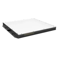
- Size
- 100-200 mm
- Type
- Standard
- Voltage
- 24 V
For tighter edge-location requirements, evaluate collimated illumination. Restricting illumination angles can reduce edge-position sensitivity caused by light wrapping around a curved profile. Performance depends on alignment and the complete imaging geometry.
The LS-2PFT120120 is a collimated backlight candidate. Confirm its usable illuminated field at the inspection plane before approving the layout.
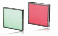
- Size
- 100-200 mm
- Type
- Collimated
- Voltage
- 24 V
Check the light's usable footprint, not just its housing dimensions. A circular beam must cover the inspection rectangle's diagonal. For an illustrative 120 mm by 24 mm rectangle, the minimum geometric diameter is approximately 122 mm, before adding alignment margin.
Use reflected lighting when the defect does not alter the silhouette. The guide to diffuse lighting for shiny parts explains an alternative for surface inspection; it does not replace profile lighting for every task.
Select the camera by sampling and shutter behavior
Browse area scan cameras using the camera finder after defining the sampling requirement. For silhouette work, monochrome imaging is usually the simplest starting point because color information is not normally required.
Prefer a global shutter when exposure may occur during motion. A rolling shutter can remain an option when the screw is stationary throughout the relevant acquisition interval and the timing has been verified.
The following catalog candidates illustrate different trade-offs, not an approved parts list for the worked example.
| Camera candidate | Catalog attributes relevant to selection | What still needs verification |
|---|---|---|
| MV-CH120-11UC | Global shutter, color, USB3 | Native pixel dimensions, effective edge sampling and trigger timing |
| MV-CS200-10UM | Rolling shutter, mono, USB3 | Native pixel dimensions and stationary acquisition timing |
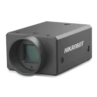
- Sensor format
- 1.1"
- Interface
- USB3
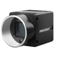
- Sensor format
- 1"
- Interface
- USB3
Do not approve either candidate from its megapixel label alone. Check native array dimensions, supported ROI behavior, exposure range, trigger implementation and sustained image transfer in the manufacturer's documentation.
For a color camera, verify performance with the intended illumination spectrum and image-processing path. Its edge response should be demonstrated rather than assumed equivalent to monochrome sampling.
Also specify the required image rate. A camera that meets resolution requirements can still miss cycle time after exposure, readout, transfer and processing are included.
Set exposure from motion, then coordinate the trigger
A global shutter prevents row-by-row geometric skew, but it does not stop motion blur. Estimate the exposure limit from object-space sampling and image-plane velocity.
Use velocity at the inspected thread region, including rotational motion where relevant. Robot travel speed is not necessarily the speed during image acquisition.
If stop-and-inspect operation reduces residual motion to 2 mm/s, the same estimate permits about 6.25 ms. That improvement is useful only if settling is repeatable and measured.
Coordinate the sequence explicitly:
- Move the screw into the inspection pose.
- Confirm that the presentation is valid and allow verified settling time.
- Establish stable illumination before exposure begins.
- Trigger acquisition and hold the required pose through the relevant acquisition interval.
- Confirm receipt of a valid image before moving or issuing a result.
If strobed lighting is necessary, verify the light's permitted operating mode, controller compatibility, pulse limits and synchronization. Do not infer strobe capability from brightness or supply voltage.
Include settling, acquisition, transfer, processing and any additional views in the cycle-time budget. A longer exposure may be acceptable if it substantially reduces lighting demands without compromising throughput.
Decide what additional views must reveal
A side silhouette is not a complete inspection of a threaded surface. A local defect may remain inside the projected outline or face away from the camera.
Define coverage from the defect specification. If only the visible thread envelope matters, a controlled side view may be sufficient. If damage anywhere around the circumference matters, evaluate indexed rotation or multiple camera views.
Two views do not automatically prove complete coverage. Establish which surfaces and defect orientations each view reveals, including areas hidden by the jaws. Change the grip or add a second handling stage if the required region remains obscured.
Registration should align valid images before extracting measurements or defect features. It should not normalize away an incorrect pitch, genuine bend or dimensional change that the inspection is supposed to reject.
Prefer explicit checks such as crest continuity, pitch consistency and local profile deviation over unrestricted image similarity alone. Keep an image-quality gate so poor focus or missing illumination cannot be reported as an acceptable screw.
Validate the inspection across real variation
Build the validation set around production variation, not repeated images of one convenient sample. Include different finishes, contamination levels, screw lengths, grip positions and permitted pose extremes.
For dimensional work, use an appropriate calibration reference at the inspection plane and compare results with an independent measurement method. Repeat calibration checks after mechanical adjustments or changes to the optical setup.
For defect detection, retain known acceptable, unacceptable and borderline parts. Record false accepts and false rejects separately, by defect class. Repeated captures of one part help quantify repeatability but do not establish coverage across production variation.
Run deliberate disturbance tests:
- Move the screw through the allowed position and depth envelope.
- Apply the maximum permitted tilt and in-plane rotation.
- Vary exposure or light output within the proposed operating limits.
- Repeat acquisition at the shortest planned settling time.
- Inspect both the shortest and longest screw variants.
- Test loss of illumination, incomplete images and failed part location.
Route uncertain images to a defined retry or reject state. Keep inspection decisions separate from machine safety functions; an ordinary inspection camera is not a personnel-protection device.
Check the specification before ordering
Complete this short checklist before committing to the camera, lens and light combination.
- Defect definition: smallest relevant feature, acceptance boundaries and required surface coverage are documented.
- Sampling: native pixels meet the requirement along both axes at the largest field of view.
- Optics: working distance, lens coverage, focus range and clearance fit the station.
- Presentation: measured grip variation stays inside the validated position and tilt envelope.
- Illumination: the usable field covers every valid pose without unacceptable edge shifts.
- Timing: exposure, settling, readout and additional views fit the cycle.
- Validation: representative defects and borderline parts are available for acceptance testing.
The right camera follows from these requirements; it does not define them. Start a camera configuration or a lighting configuration with your calculated field and sampling target. For a coordinated specification, send the defect dimensions, screw drawing, pose envelope and cycle time through application support.
Questions
How many megapixels does a screw thread inspection camera need?
There is no universal megapixel requirement. Divide the required field of view by the object-space sampling needed for your smallest defect. Check both sensor axes, because a camera can have enough total pixels but too few along the screw. Validate the resulting images with representative defects before approving the selection.
Can a camera ROI eliminate the need for a backlight?
No. An ROI changes which pixels are acquired or processed; it does not improve illumination consistency or recover detail lost through poor contrast. Controlled lighting remains necessary for repeatable edge detection. A physical light mask can reduce stray illumination, but it performs a different function from an image ROI.
Should the camera have a global shutter?
A global shutter is preferable when the screw may move during acquisition. A rolling shutter can be considered for a verified stationary presentation. Neither shutter type eliminates exposure blur, so exposure time must still be checked against residual motion and the required object-space sampling.
Can image alignment compensate for a tilted screw?
Registration can compensate for translation and rotation within the image plane when sufficient detail and image margin remain. Out-of-plane tilt changes projection and focus across the screw. Correct the presentation mechanically or validate a geometry-aware measurement method rather than expecting ordinary reference-image alignment to remove those changes.
When does thread inspection require multiple views?
Multiple views are needed when required defects can remain hidden inside the silhouette, face away from the camera or sit behind the gripper. Choose view angles and handling stages from a coverage study using representative damage. A fixed number of views does not automatically establish complete circumferential inspection.