
Making scratches stand out on machined metal with four-sided lighting
A reflective metal plate can look uniformly grey while a shallow scratch disappears into its finish. Four adjustable bar lights change the direction of illumination so scratches and hole edges return bright contrast to the camera.
Choose lighting direction before adding resolution.
- Test lightFour-sided adjustable bar light
- Housing (spec)230 × 230 × 37 mm
- EvidenceBright scratch contrast in the capture
- MethodDirectional reflected light
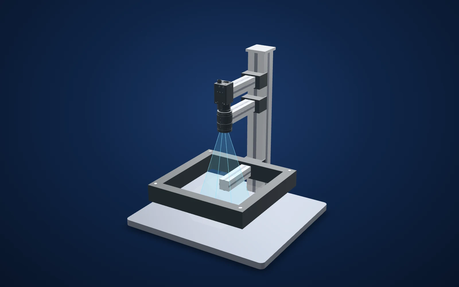 Drag to rotate · scroll to zoom
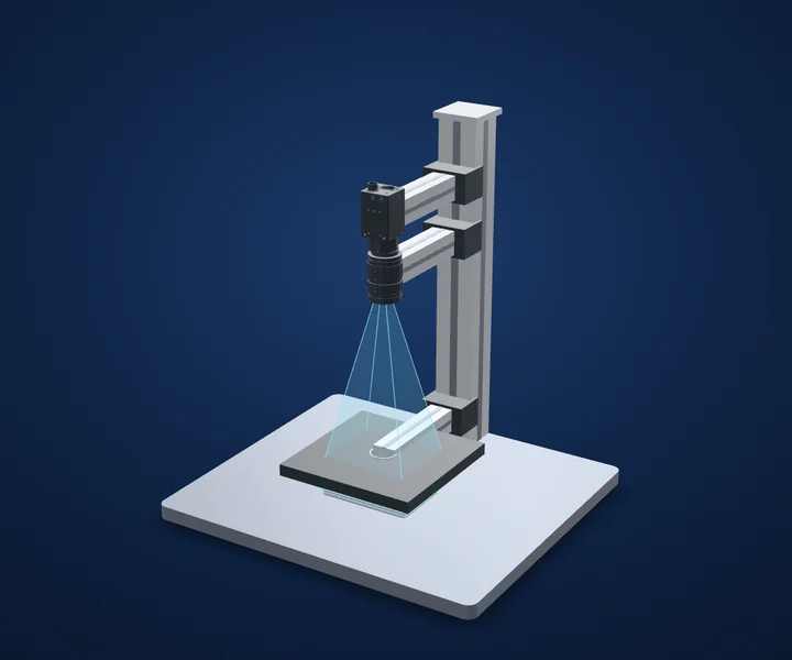
Camera and CAD lens geometry are published models where available. Light housings use printed dimensions; fixtures, parts, beam shapes and spacing illustrate the inspection principle. This is not an optical simulation or a dimensioned installation drawing.
Evidence you can inspect
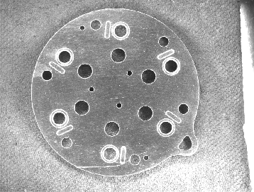
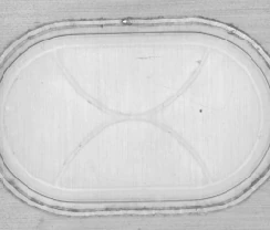
Bright scratches and hole edges are visible in the supplied camera capture.
The application sheet describes scratch contrast; it gives no numerical detection result.
Application-lab image, not a customer production acceptance test.
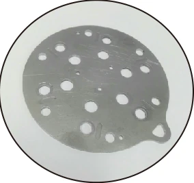
What the camera saw
Cropped from the source test sheet; original test annotations are retained. Captures are not generated or enhanced. Drag the comparison slider or use the image buttons.
The challenge
Machining marks, holes and scratches all scatter light differently. A bright image alone does not establish a useful defect signal.
The trial has to separate a scratch from normal surface texture, including scratches running in different directions.
How it was solved
The application sheet pairs the LS-4BRM230 in white with a circular machined plate. Its camera capture shows bright scratches and bright edges around the holes against the darker metal surface.
The four-sided light allows each side to be controlled independently and its angle to be adjusted. For a production trial, compare directions separately before deciding which combination preserves the defect contrast.
Why it works
- 1
A local change in surface slope redirects light. The scratch can return light into the lens while the surrounding finish returns less.
- 2
Lighting from several directions gives more options when the scratch orientation is not fixed. Independent control allows those directions to be tested.
- 3
The evidence is the observed image contrast. The sheet does not establish a minimum scratch width, inspection rate or detection percentage.
What to validate on your part
A useful sample image is the starting point. These are the checks that turn the concept into a defensible inspection.
- 01
Rotate the defect
Capture known scratches at several orientations and test each light direction.
- 02
Separate texture from damage
Include acceptable machining marks and scratches close to your rejection limit.
- 03
Set the acceptance rule
Measure contrast and false calls at the final exposure, aperture and line speed.
The set-up and the parts
| Test light | LS-4BRM230, white |
|---|---|
| Housing (printed) | 230 × 230 × 37 mm |
| Supply (printed) | 24 V |
| Camera and lens | Not identified in the application sheet; proposed parts below |
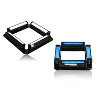
White four-sided combined bar light used in the application sheet. Housing: 230 × 230 × 37 mm; individually controllable sides.
$159.00In proposed setup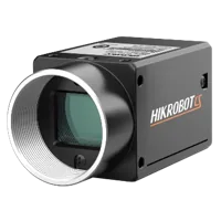
5 MP monochrome area-scan camera; a starting point for a contrast trial. Confirm sampling against your smallest defect.
$819.00In proposed setup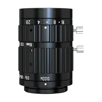
16 mm C-mount macro lens, 0.25x to 0.03x magnification. Confirm field of view and working distance on your part.
$319.00In proposed setup"Tested" identifies the part named in the source. "Our pick" is a proposed alternative or supporting part. The quote includes only cards marked "In proposed setup", with the quantities shown; other test arrangements are separate. Confirm colour, optics, controllers, power supplies, cables and mounting before ordering.
About this case study: the photos and camera images come from the application laboratory of the maker of the lighting and optics we sell, imaged on the parts shown; your results depend on your part, camera and set-up. This is an application-lab study, not a LumaSpec customer deployment. Source figures are reported results; proposed components require a fresh trial. The 3D scene illustrates the arrangement and does not simulate imaging performance.
More case studies
Battery welds and tabs
Control what shiny metal reflects.
- LightFlat dome, 100 × 100 mm emitting
- Size140 × 140 × 11.5 mm
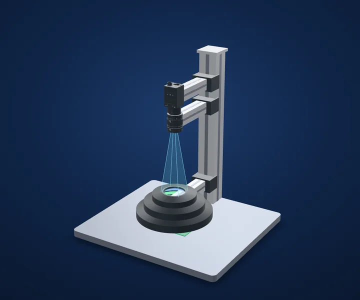
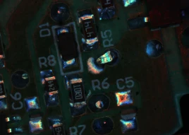
PCB solder joints with an RGB AOI light
Use lighting angle to make solder shape visible.
- LightAOI, 160 mm outside, 45 mm aperture
- Height55 mm
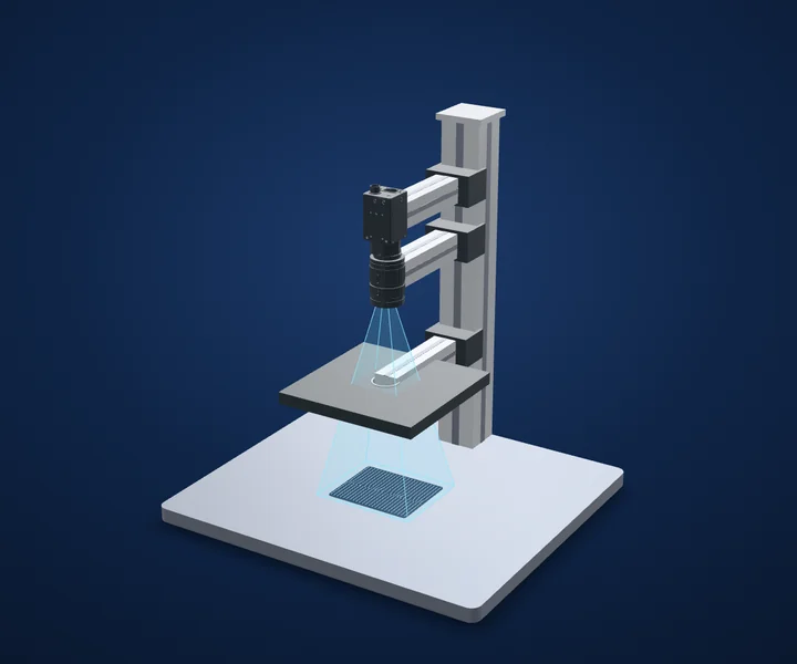
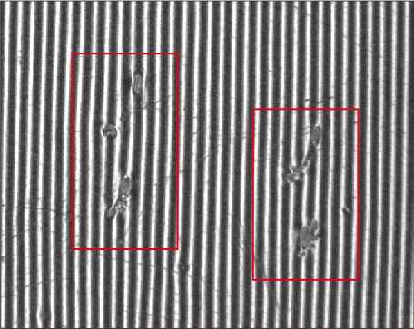
Polarizer-film defects in reflected stripes
Give a featureless surface a pattern to reflect.
- Light-to-part (as tested)100 mm
- Exposure (as tested)8,000 µs / 8 ms
Make the next trial specific.
Tell us the part size, smallest defect or tolerance, available working distance, material and line speed. Include what a good part and a reject look like.
Discuss your applicationConfigure a system