
Polarizer-film defects: sharper reflected stripes reveal local distortion
Small surface changes are hard to see in a glossy, nearly featureless film. A striped light provides a pattern to inspect: local bends and interruptions in its reflection reveal where the surface changes.
Give a featureless surface a pattern to reflect.
- Light-to-part (as tested)100 mm
- Exposure (as tested)8,000 µs / 8 ms
- ComparisonEarlier vs revised striped light
- Housing (spec)140 × 140 × 11.5 mm
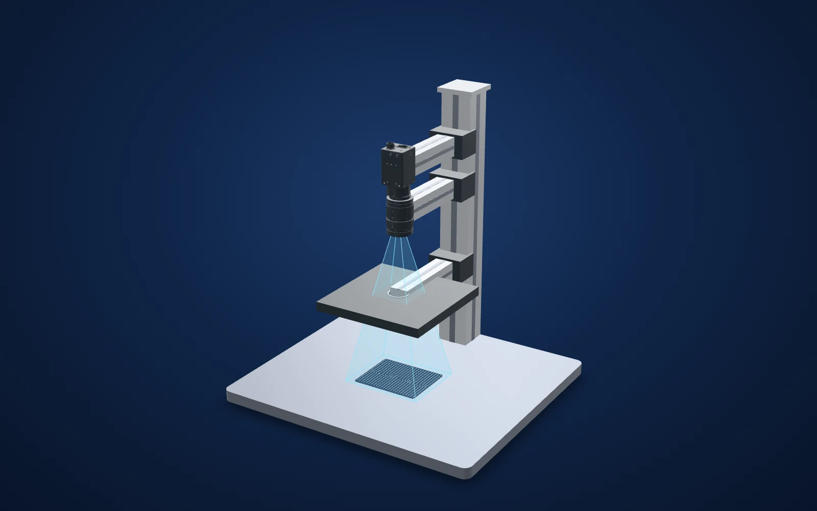 Drag to rotate · scroll to zoom
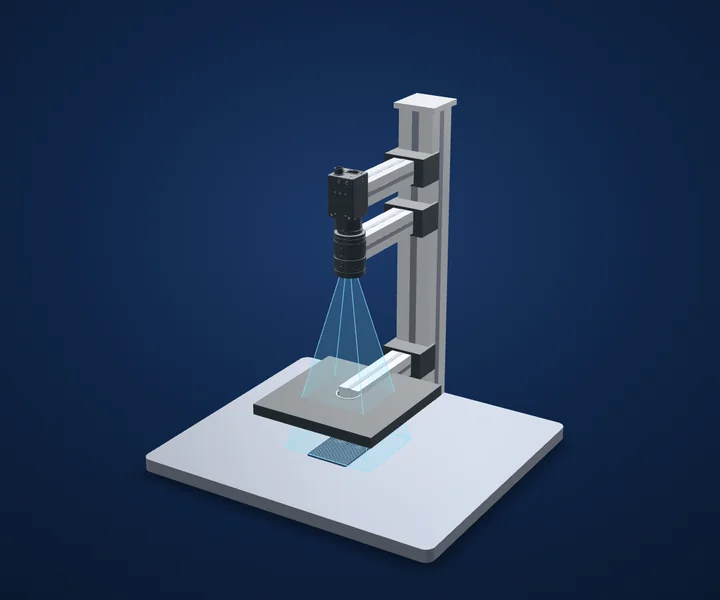
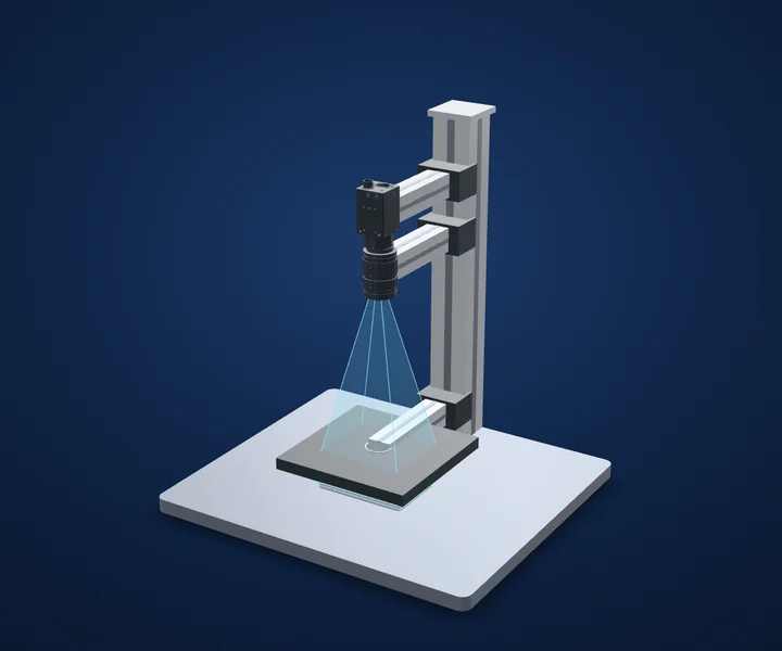
Camera and CAD lens geometry are published models where available. Light housings use printed dimensions; fixtures, parts, beam shapes and spacing illustrate the inspection principle. This is not an optical simulation or a dimensioned installation drawing.
Evidence you can inspect
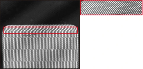
The supplied comparison shows stronger stripe separation and local pattern distortion.
100 mm light-to-part distance and 8,000 µs exposure are printed on the test sheet.
The sheet does not report defect depth or a calibrated measurement capability.
What the camera saw
Cropped from the source test sheet; original test annotations are retained. Captures are not generated or enhanced. Drag the comparison slider or use the image buttons.
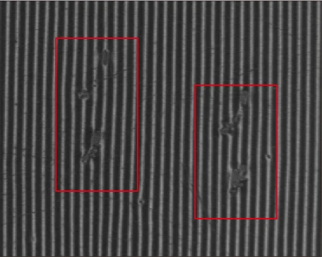
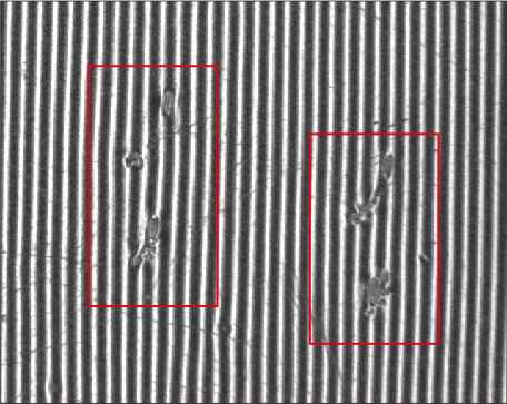 Earlier striped lightRevised striped light
Revised striped light: White LS-2LFM100: sharper reflected stripes and clearer local disturbances; red boxes are the original test annotations.
The challenge
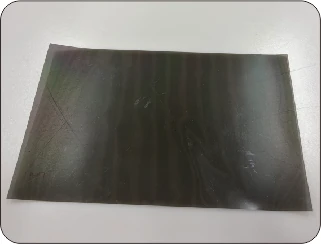
A smooth polarizer film offers little natural texture. A crease or local surface change can remain subtle under an even white field.
An inspection based on reflected stripes needs the stripes themselves to be sharp and stable; blurred patterns make the surface harder to interpret.
How it was solved
The application sheet compares an earlier striped light with the white LS-2LFM100 at a light-to-part distance of 100 mm and an exposure of 8,000 µs. The revised image has clearer black-to-white stripe separation in the marked areas.
Use the reflected pattern as a reference. Local distortion is a candidate defect signal; confirm it using known good and known defective films before setting an acceptance threshold.
Why it works
- 1
A smooth reflective region returns an orderly stripe pattern. A local change in slope shifts or bends that pattern.
- 2
Sharper stripes make small changes easier to locate in the image. This is reflected-pattern inspection, rather than a direct height measurement.
- 3
The two supplied captures demonstrate a lighting comparison. No calibrated depth, smallest defect size or production yield is stated.
What to validate on your part
A useful sample image is the starting point. These are the checks that turn the concept into a defensible inspection.
- 01
Stabilize the film
Control tension, tilt and flutter so normal motion does not look like a defect.
- 02
Keep the stripes resolved
Test aperture, focus and sampling so adjacent stripes remain separate.
- 03
Check the smallest reject
Compare known creases and surface defects against acceptable film variation.
The set-up and the parts
| Test light | LS-2LFM100, white |
|---|---|
| Light-to-part distance (test) | 100 mm |
| Exposure (test) | 8,000 µs (8 ms) |
| Camera and lens | Not identified; proposed starting points below |
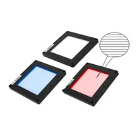
Revised striped shadowless light used in the comparison, white; 100 × 100 mm emitting area.
$329.00In proposed setup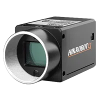
5 MP monochrome area-scan camera; a starting point for a contrast trial. Confirm sampling against your smallest defect.
$819.00In proposed setup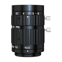
16 mm C-mount macro lens, 0.25x to 0.03x magnification. Confirm field of view and working distance on your part.
$319.00In proposed setup"Tested" identifies the part named in the source. "Our pick" is a proposed alternative or supporting part. The quote includes only cards marked "In proposed setup", with the quantities shown; other test arrangements are separate. Confirm colour, optics, controllers, power supplies, cables and mounting before ordering.
About this case study: the photos and camera images come from the application laboratory of the maker of the lighting and optics we sell, imaged on the parts shown; your results depend on your part, camera and set-up. This is an application-lab study, not a LumaSpec customer deployment. Source figures are reported results; proposed components require a fresh trial. The 3D scene illustrates the arrangement and does not simulate imaging performance.
More case studies
Screen-film creases and local deformation
Inspect the change in reflection, not just the film colour.
- Test lightLS-2LFM100, white
- SignalLocal stripe deformation
Battery welds and tabs
Control what shiny metal reflects.
- LightFlat dome, 100 × 100 mm emitting
- Size140 × 140 × 11.5 mm
PCB solder joints with an RGB AOI light
Use lighting angle to make solder shape visible.
- LightAOI, 160 mm outside, 45 mm aperture
- Height55 mm
Make the next trial specific.
Tell us the part size, smallest defect or tolerance, available working distance, material and line speed. Include what a good part and a reject look like.
Discuss your applicationConfigure a system