
See the problem.
Understand the setup.
Machine-vision application studies with real camera captures, explorable 3D arrangements and the reasoning behind each lighting and optics choice.
Find your application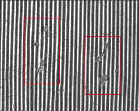 Featured study · Polarizer film
Give a featureless surface a pattern to reflect →
Start with the feature you need to see.
These are application-lab demonstrations from the makers of the components we sell. Each study identifies the tested parts, our proposed alternatives and what still needs to be validated on your part.
Applications using
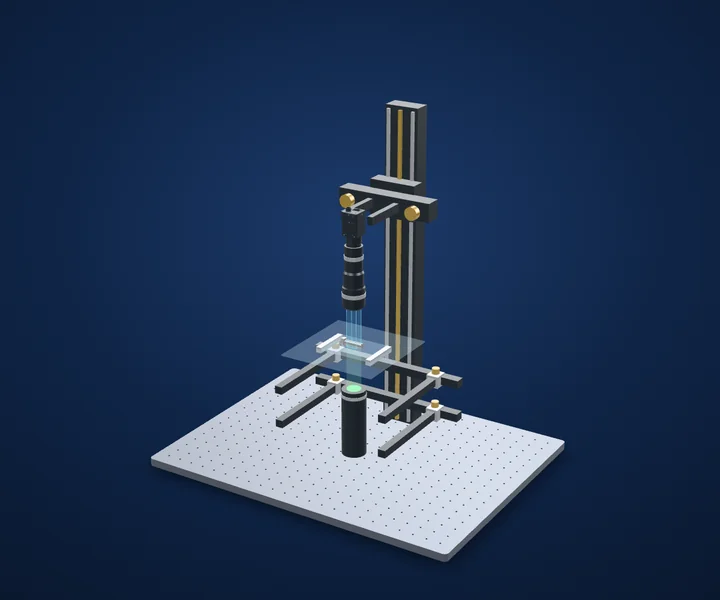
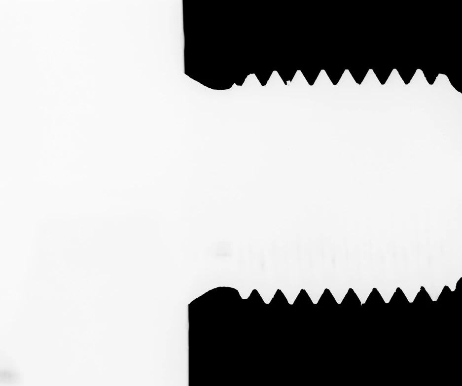
Screw thread pitch with telecentric optics
Stabilize scale and edge contrast before judging a tolerance.
- Gezichtsveld19.34 × 16.21 mm
- Image2456 × 2058 px
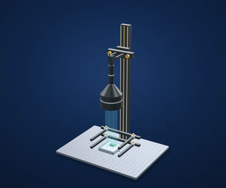
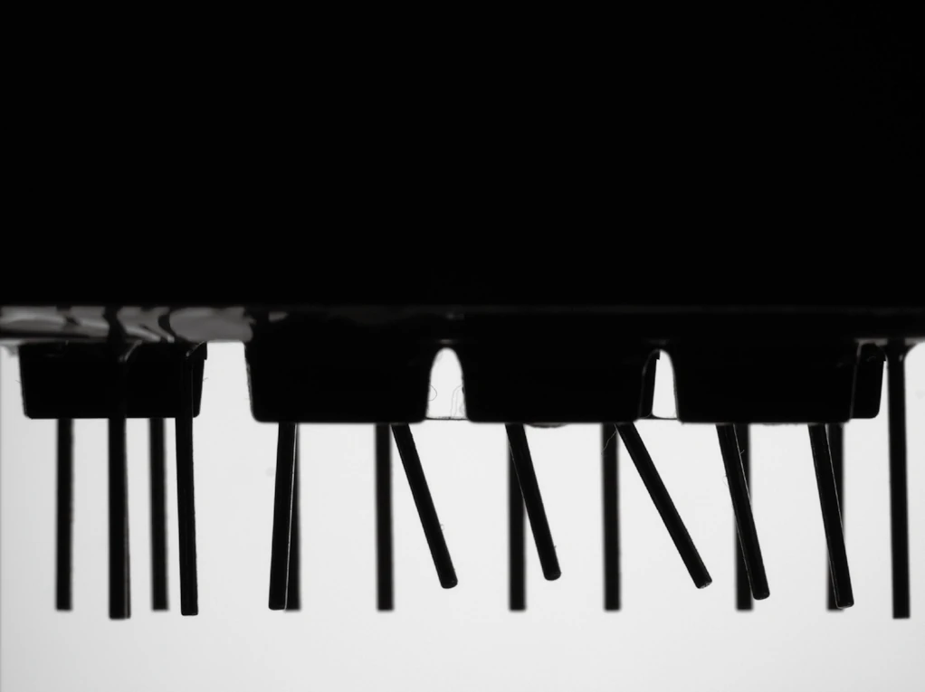
Bent pins on connectors and boards
Separate real pin lean from perspective.
- Gezichtsveld50.46 × 37.85 mm
- Image2592 × 1944 px
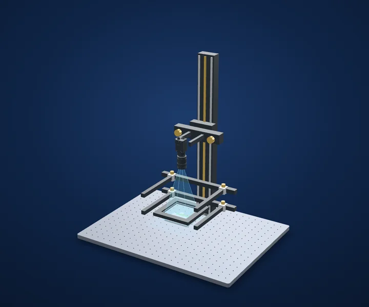
Battery welds and tabs
Control what shiny metal reflects.
- VerlichtingFlat dome, 100 × 100 mm emitting
- Afmeting140 × 140 × 11.5 mm
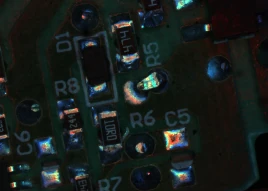
PCB solder joints with an RGB AOI light
Use lighting angle to make solder shape visible.
- VerlichtingAOI, 160 mm outside, 45 mm aperture
- Hoogte55 mm
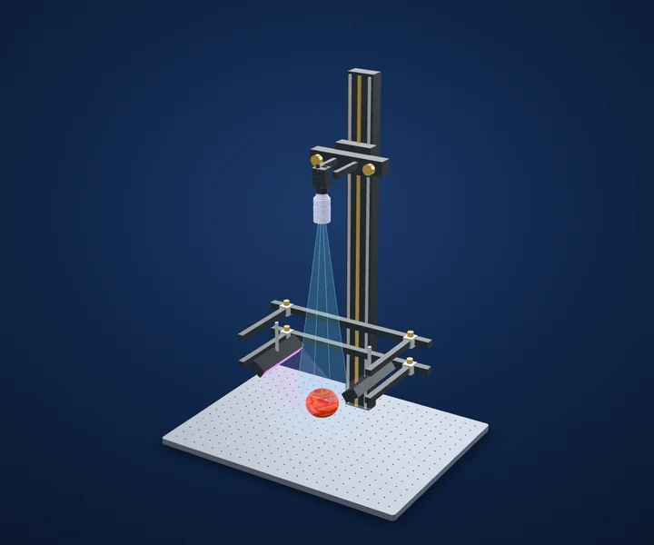
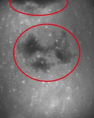
Apple bruises: NIR vs SWIR
Match the wavelength, sensor and optics as one system.
- NIR940 nm
- SWIR1550 nm
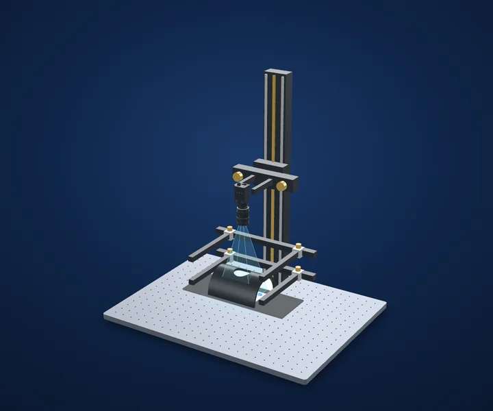
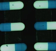
Contamination in blister packs
Reduce glare before searching for a dark speck.
- VerlichtingArch shadowless, 125 × 70 mm emitting
- Werkafstand5–50 mm (light spec)
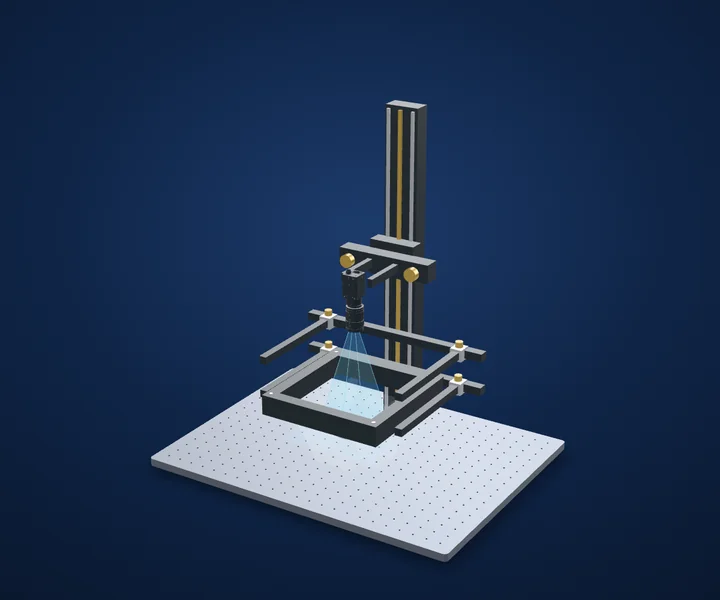
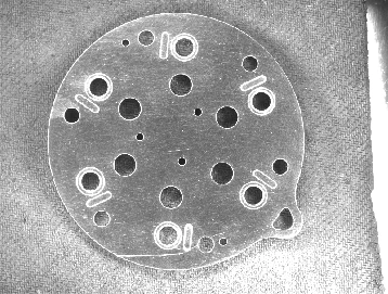
Scratches on machined metal
Choose lighting direction before adding resolution.
- Test lightFour-sided adjustable bar light
- Housing (spec)230 × 230 × 37 mm
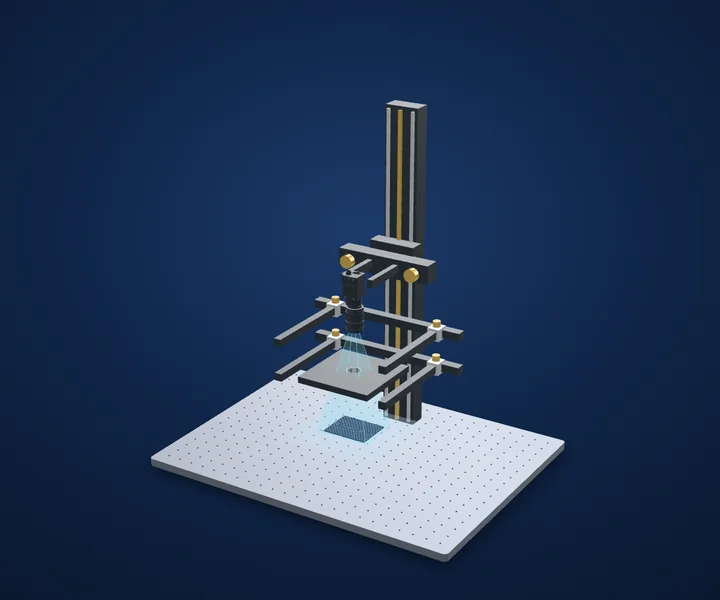
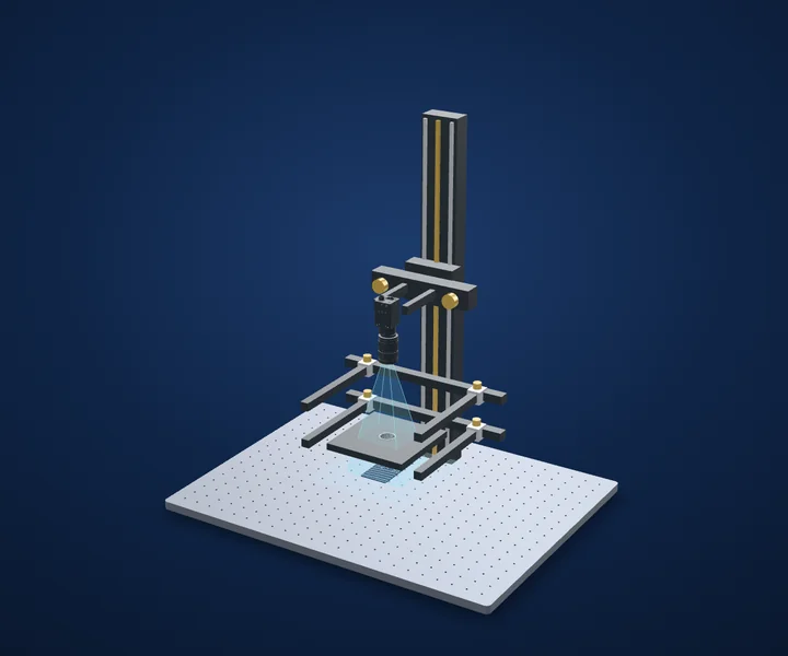
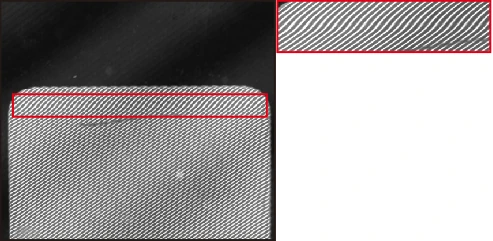
Polarizer-film defects in reflected stripes
Give a featureless surface a pattern to reflect.
- Light-to-part (as tested)100 mm
- Exposure (as tested)8,000 µs / 8 ms
Screen-film creases and local deformation
Inspect the change in reflection, not just the film colour.
- Test lightLS-2LFM100, white
- SignalLocal stripe deformation
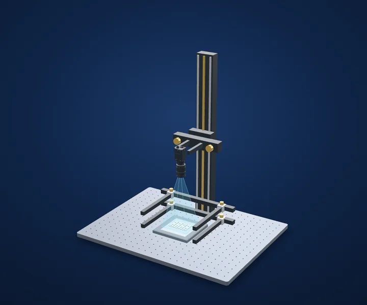
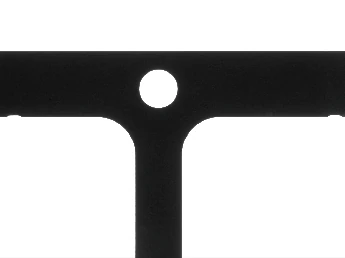
Stamped-metal terminal contours
Use a silhouette when the requirement is shape.
- Test lightWhite thin-panel backlight
- Housing (spec)140 × 140 × 9.5 mm
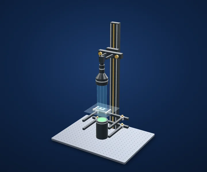
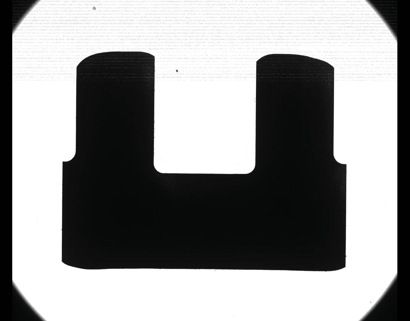
A shaft silhouette with matched telecentric optics
Treat the lens, collimated light and fixture as one calibrated measurement system.
- Source field47.52 × 39.85 mm
- Source image2452 × 2056 px
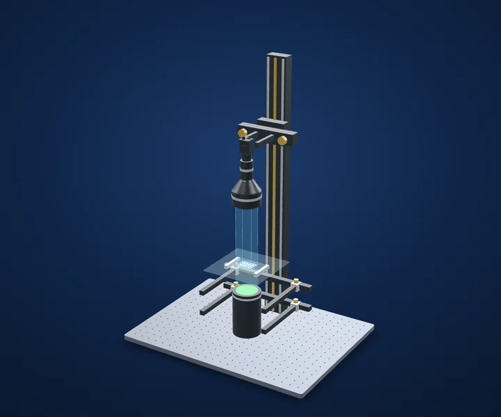
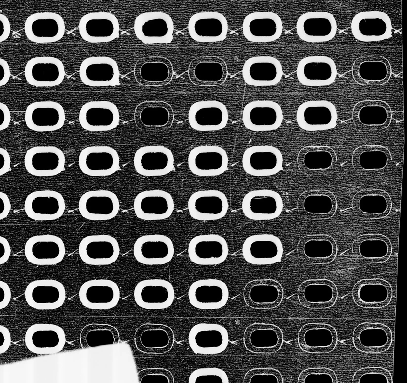
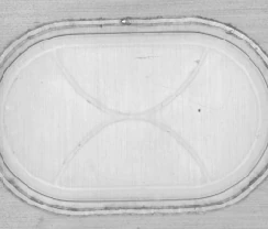
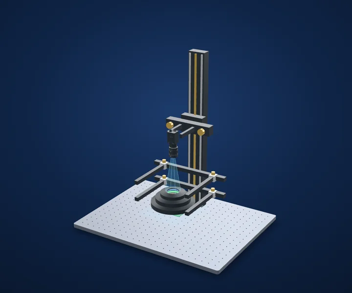
Inspecting oval apertures with telecentric optics
Treat the lens, collimated light and fixture as one calibrated measurement system.
- Source field51.16 × 38.84 mm
- Source image1628 × 1236 px
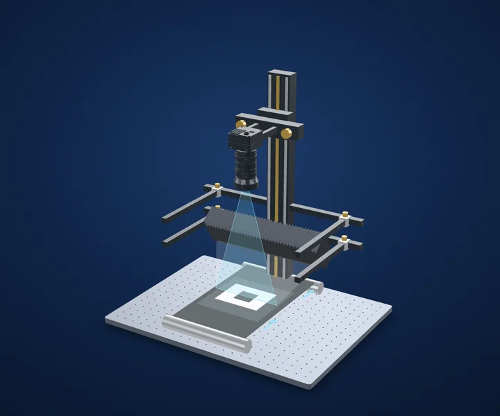
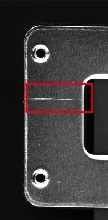
A line-scan station for metal surface scratches
The lighting reveals the feature; synchronized material travel turns the line into a useful image.
- Proposed camera2048 pixels · mono
- ObjectiefinterfaceM42 × 1 · 12 mm flange
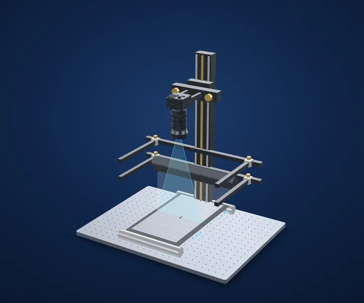
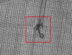
A line-scan station for textile surface defects
The lighting reveals the feature; synchronized material travel turns the line into a useful image.
- Proposed camera2048 pixels · mono
- ObjectiefinterfaceM42 × 1 · 12 mm flange
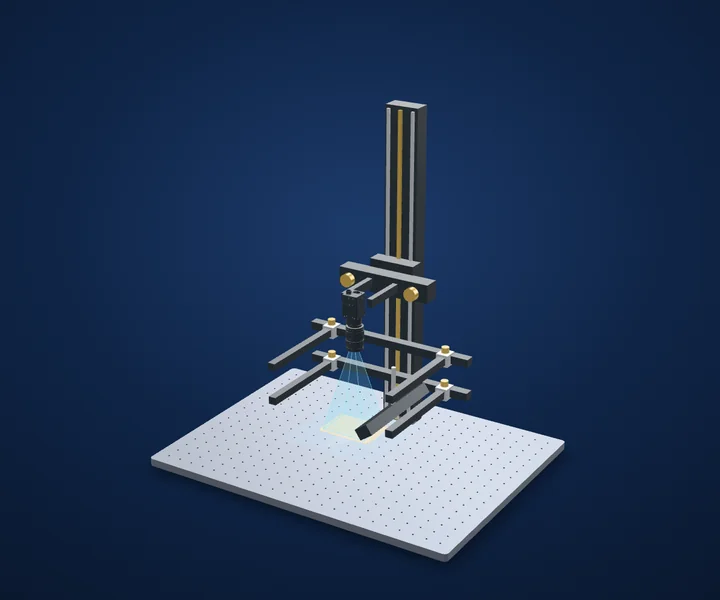
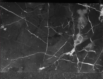
Ceramic-tile pattern visibility
Prove lighting uniformity before classifying a decorative pattern.
- Proposed light housing (spec)196 × 20.3 × 27 mm
- EvidenceReal lighting-lab captures
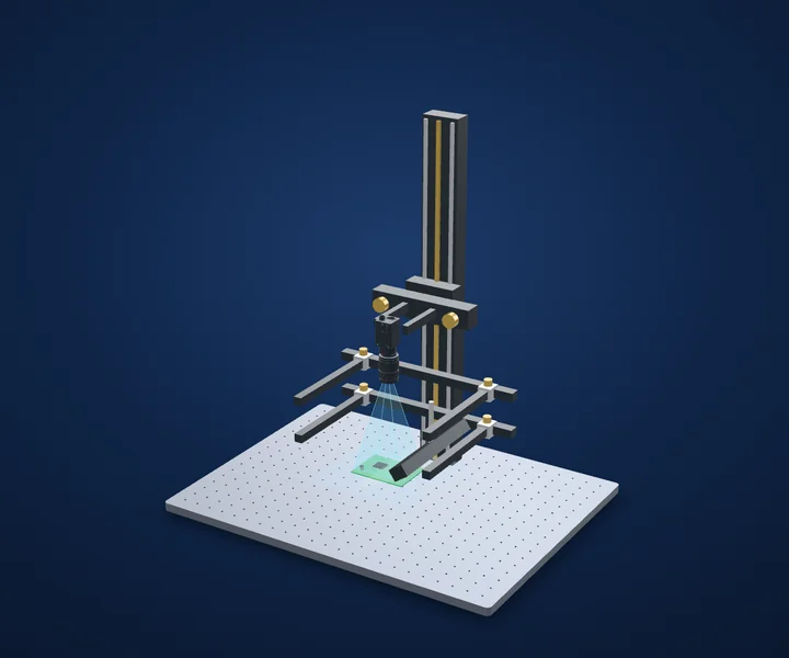
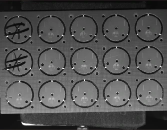
Even light across repeated PCB panels
A repeated feature needs repeatable illumination wherever it lands.
- Proposed light housing (spec)196 × 20.3 × 27 mm
- EvidenceReal lighting-lab captures
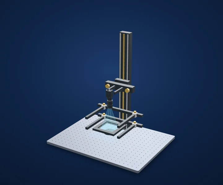
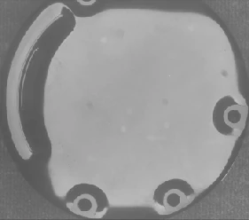
Black-painted metal under a flat dome
Make the reflected field consistent before calling a surface defect.
- Proposed light housing (spec)140 × 140 × 11.5 mm
- EvidenceReal lighting-lab captures
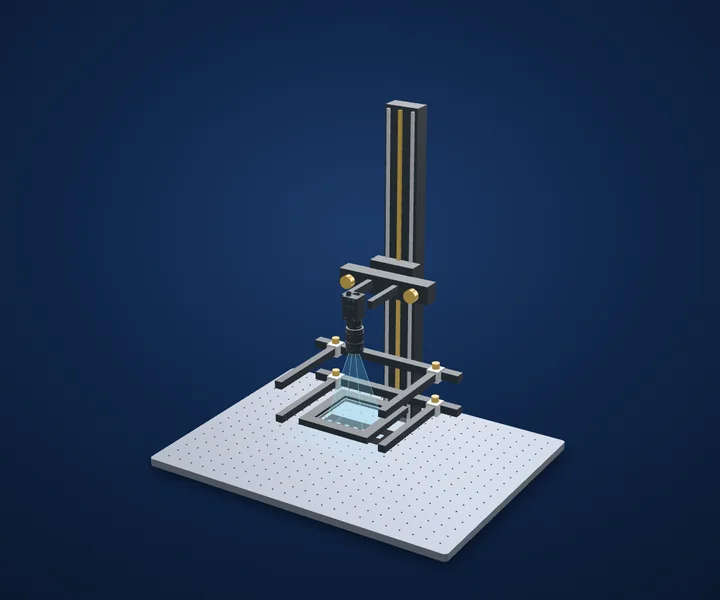
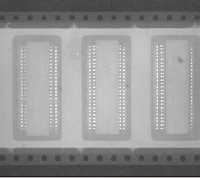
Chip pockets beneath reflective cover film
Treat cover-film glare as an optical problem before changing the algorithm.
- Proposed light housing (spec)140 × 140 × 11.5 mm
- EvidenceReal lighting-lab captures
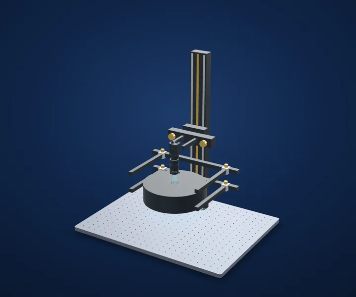
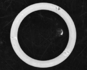
Rubber-gasket defects under a multi-angle ring
Use multi-angle light to test visibility around the entire seal.
- Proposed light housing (spec)Ø225 × 64 mm
- EvidenceReal lighting-lab captures
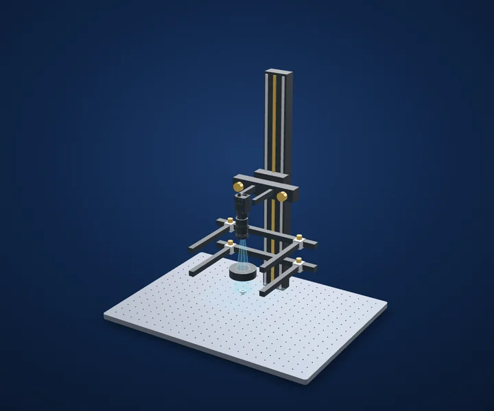
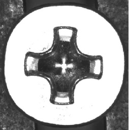
Screw-head shape at two ring-light angles
Choose lighting angle for the feature that actually drives the decision.
- Proposed light housing (spec)Ø70 × 20.5 mm
- EvidenceReal lighting-lab captures
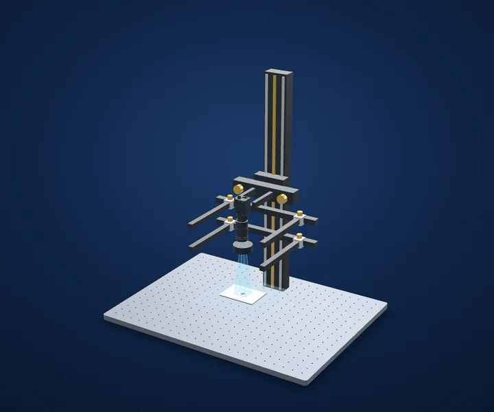
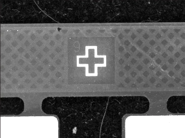
Bright PCB fiducial on a textured background
A visible fiducial becomes a positioning tool only after calibration and repeatability checks.
- Proposed light housing (spec)Ø50 × 17.5 mm
- EvidenceReal lighting-lab captures
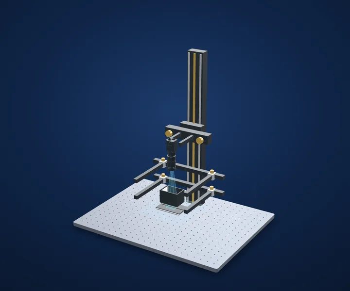
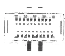
Repeated connector contacts under coaxial light
Start with a clear image of the observable contact geometry.
- Proposed light housing (spec)74 × 50 × 50 mm
- EvidenceReal lighting-lab captures
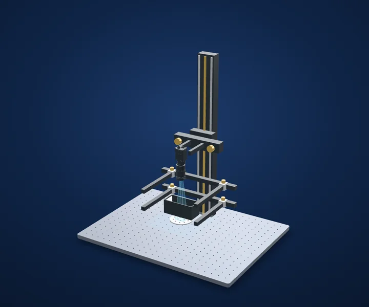
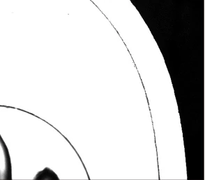
Reflective tablet-shell edge under coaxial light
A clear contour still needs an unambiguous physical datum.
- Proposed light housing (spec)111 × 50 × 50 mm
- EvidenceReal lighting-lab captures
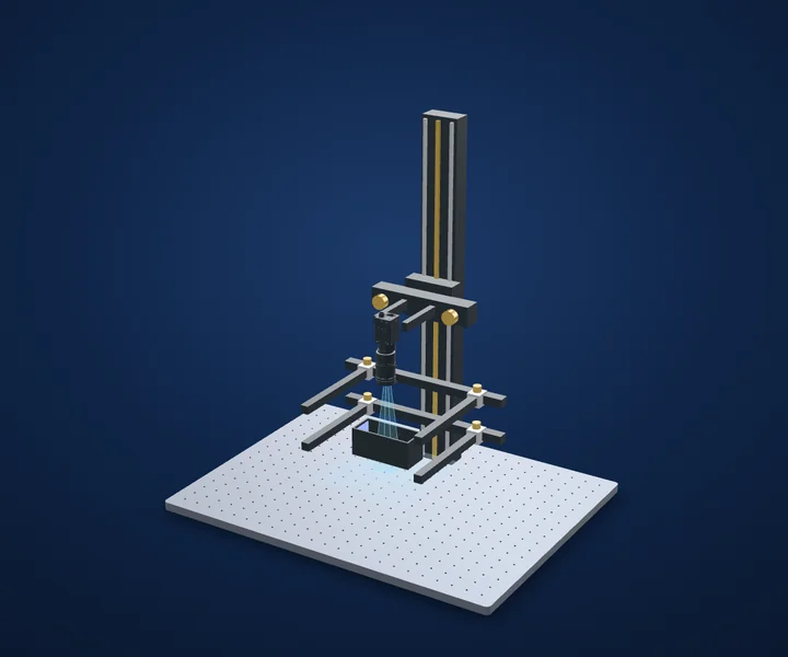
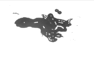
Dark residue on a bright glass field
Prove the difference between unacceptable residue and acceptable background.
- Proposed light housing (spec)105.5 × 46 × 47 mm
- EvidenceReal lighting-lab captures
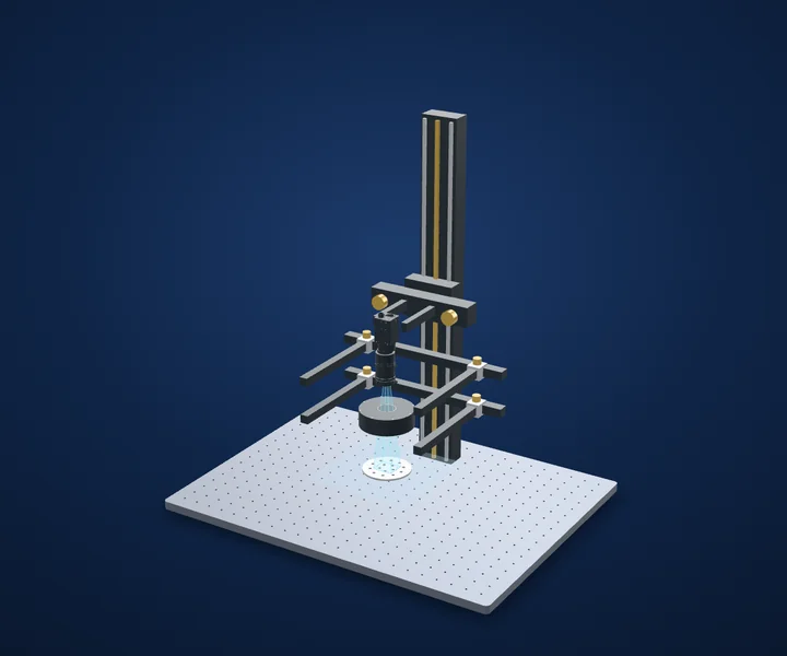
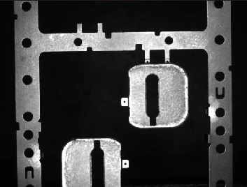
Stamped metal features under diffuse ring light
Locate the part from features that survive normal manufacturing variation.
- Proposed light housing (spec)Ø90 × 28 mm
- EvidenceReal lighting-lab captures
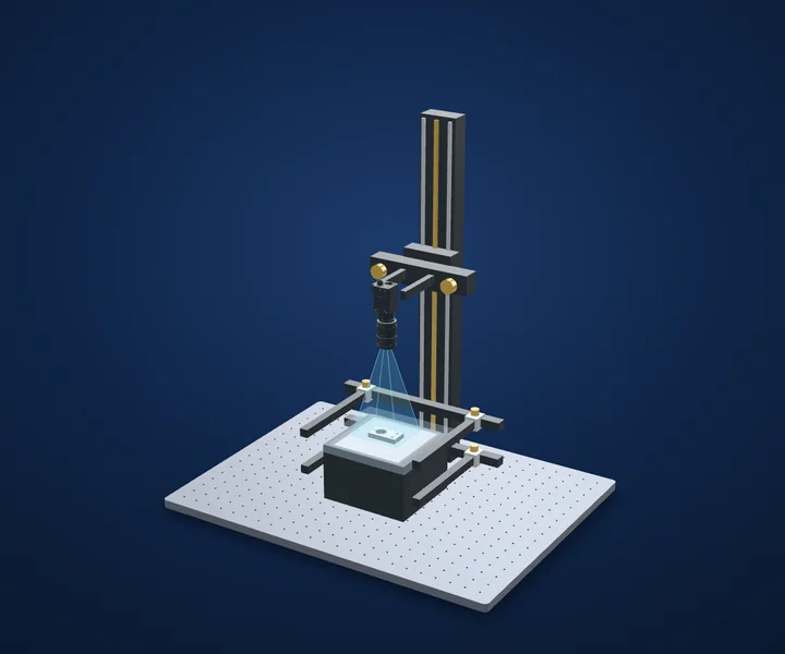
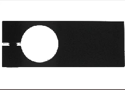
Shaft-sleeve edges under two backlights
Translate light output into a measured exposure budget.
- Proposed light housing (spec)151 × 137 × 96.52 mm
- EvidenceReal lighting-lab captures
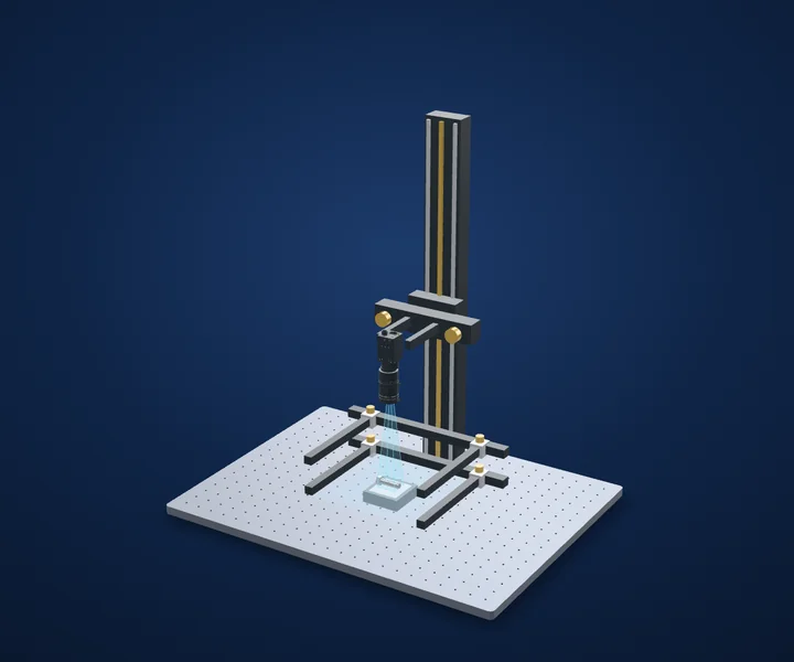
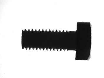
Screw outline with a collimated panel
Collimated lighting improves a silhouette; stable magnification is a separate lens decision.
- Proposed light housing (spec)64 × 64 × 19 mm
- EvidenceReal lighting-lab captures
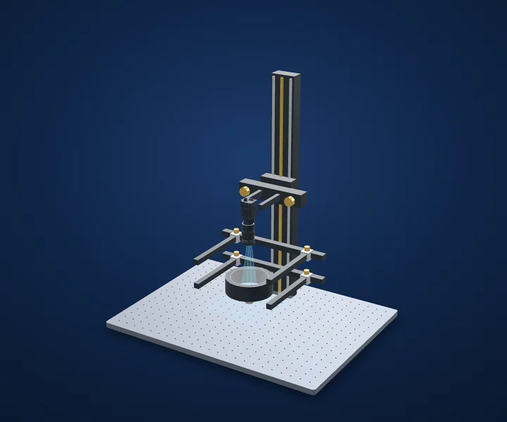
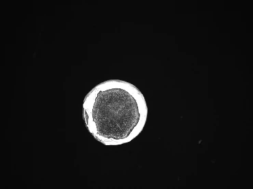
Cylindrical battery-end wrap under a ring light
A useful packaging image supports a defined appearance decision.
- Proposed light housing (spec)Ø120 × 40 mm
- EvidenceReal lighting-lab captures
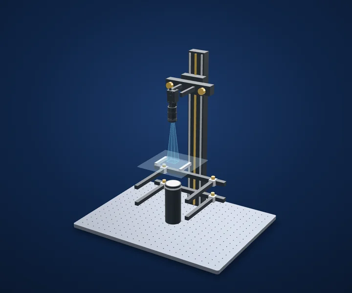
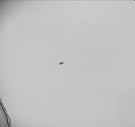
Glass inclusions under a directional spot backlight
A dark spot is an observed image feature until its physical cause is verified.
- Proposed light housing (spec)Ø58 × 150.5 mm
- EvidenceReal lighting-lab captures
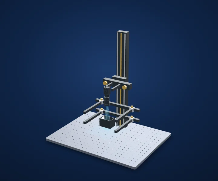
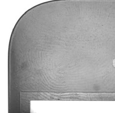
Mobile cover-glass contour under coaxial light
Choose the viewing geometry around a clearly defined edge datum.
- Proposed light housing (spec)74 × 50 × 50 mm
- EvidenceReal lighting-lab captures
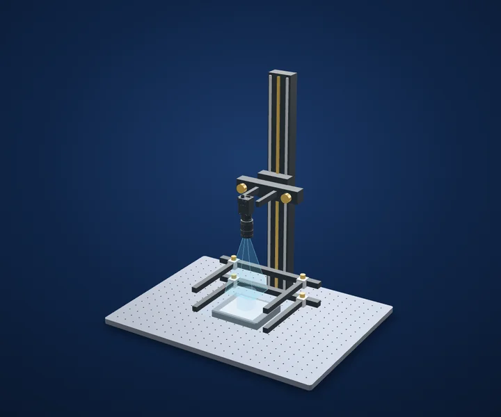
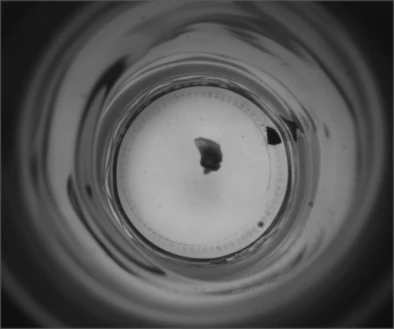
Foreign matter in a bottle bottom
Build the clean-bottle variation into the test before setting a dark-spot threshold.
- MethodTransmitted white backlight
- EvidenceReal application-lab capture
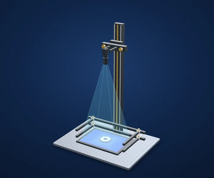
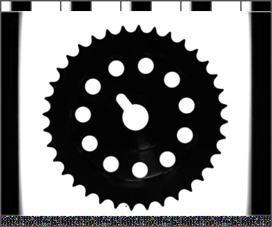
Gear teeth and bore contours
A clean silhouette supports edge finding; calibration makes those edges useful for gauging.
- MethodBlue transmitted backlight
- EvidenceReal application-lab capture
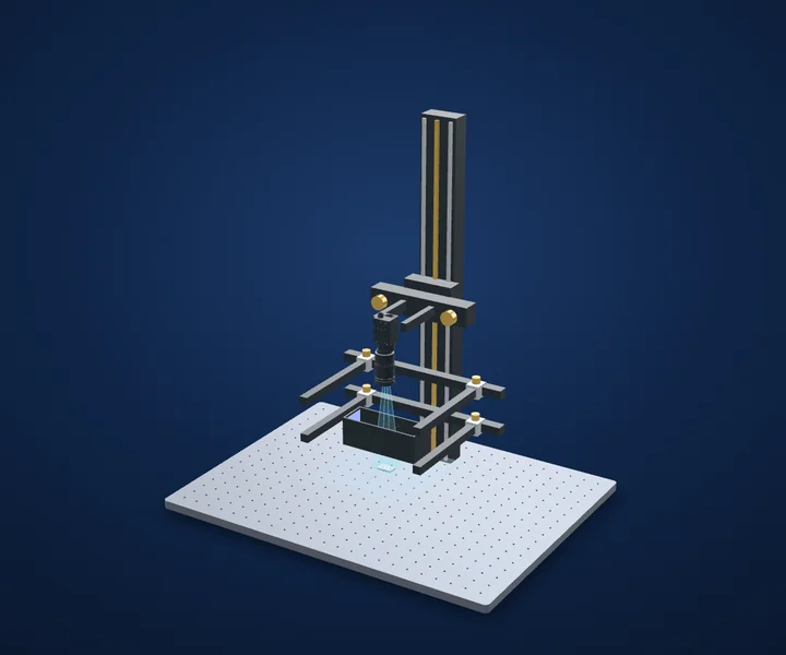
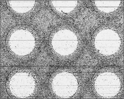
Contamination in small holes
Test the full bore depth before treating a bright hole as an unobstructed one.
- MethodBlue coaxial illumination
- EvidenceReal application-lab capture
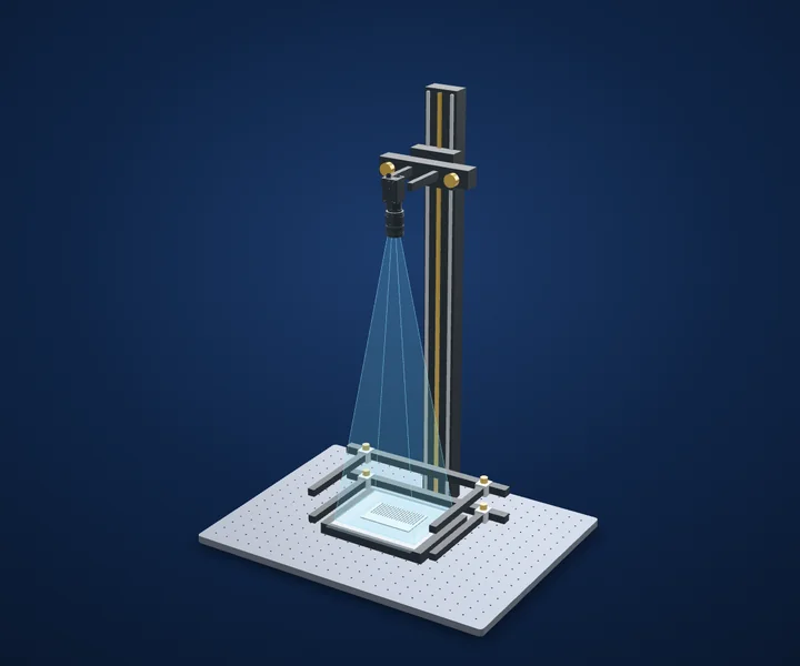
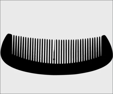
Comb tooth and gap inspection
Choose sampling for the smallest gap that must remain open.
- MethodWhite parallel backlight
- EvidenceReal application-lab capture
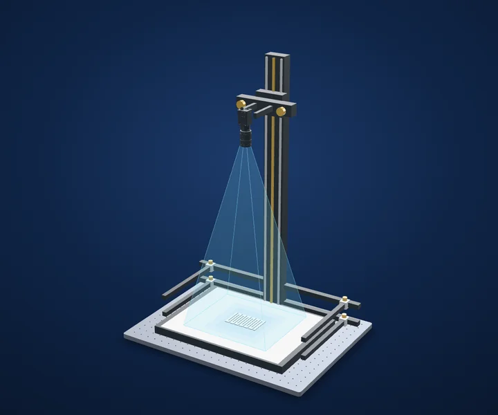
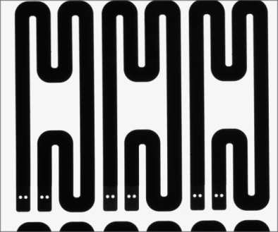
Printed resistor track appearance
A visual pattern inspection complements an electrical test; it does not replace it.
- MethodTransmitted white backlight
- EvidenceReal application-lab capture
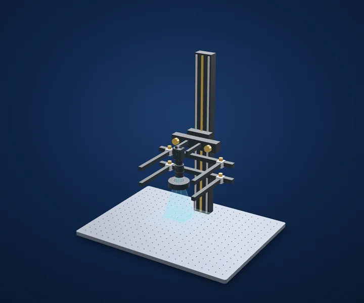
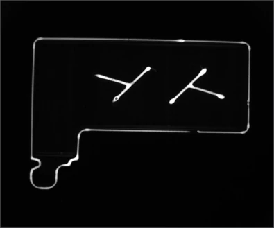
UV adhesive bead continuity on glass
Use fluorescence contrast to inspect the bead shape, then validate the bond by the required method.
- Method365 nm UV excitation
- EvidenceReal application-lab capture
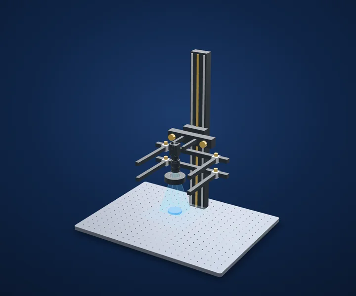
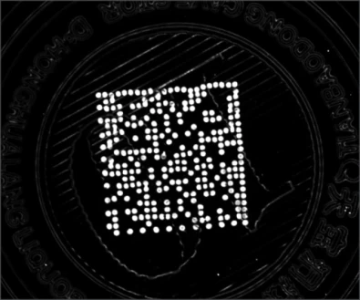
UV bottle-cap code imaging
Prove the UV image first, then measure the reader performance.
- Method365 nm UV ring illumination
- EvidenceReal application-lab capture
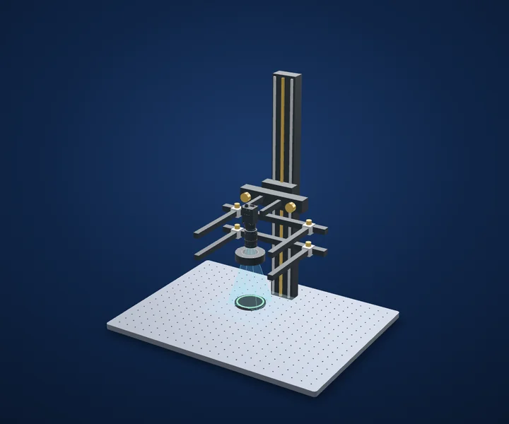
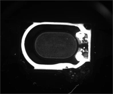
UV adhesive on a loudspeaker
Inspect where the bead must be, not just how much of the image is bright.
- Method365 nm UV excitation
- EvidenceReal application-lab capture
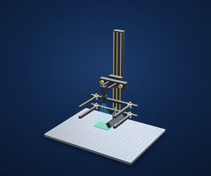
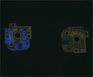
UV adhesive presence on circuit boards
Identify what fluoresces before deciding what the bright regions mean.
- Method365 nm UV material contrast
- EvidenceReal application-lab capture
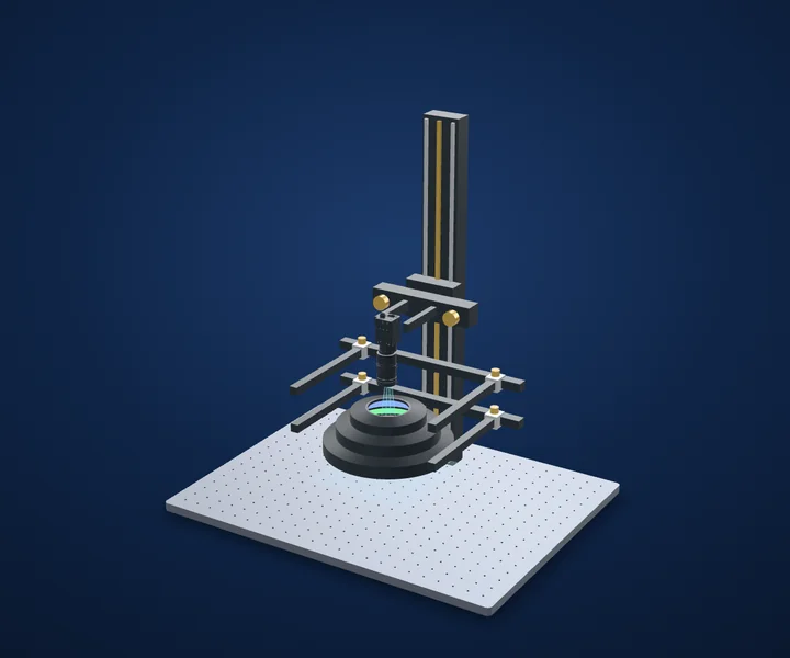
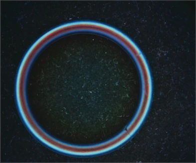
O-ring appearance with RGB angles
Use coloured angles to create a repeatable appearance signal, then validate the decision.
- MethodThree-angle RGB reflection
- EvidenceReal application-lab capture
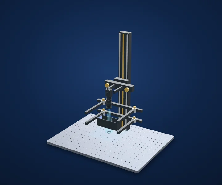
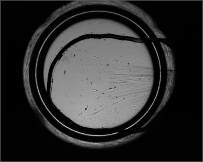
Surface marks on optical lenses
Choose the light path for the defect class instead of treating every visible spot alike.
- MethodBlue coaxial reflected light
- EvidenceReal application-lab capture
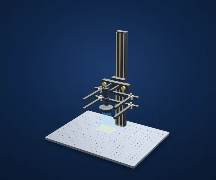
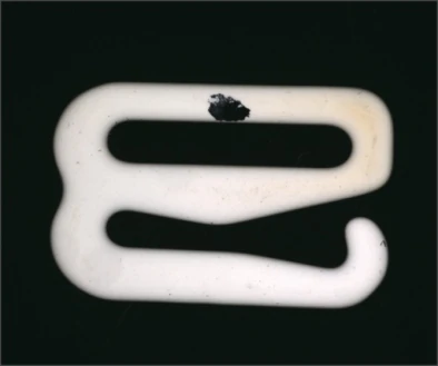
Ceramic glaze appearance under polarized light
Stabilize glare and colour processing before assigning a surface threshold.
- MethodWhite polarized ring illumination
- EvidenceReal application-lab capture
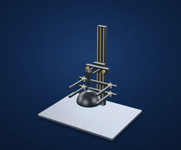
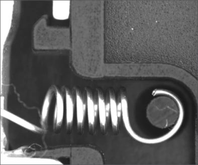
Spring and hook assembly under dome lighting
Make the attachment visible, then validate the mechanical requirement independently.
- MethodDiffuse white dome
- EvidenceReal application-lab capture
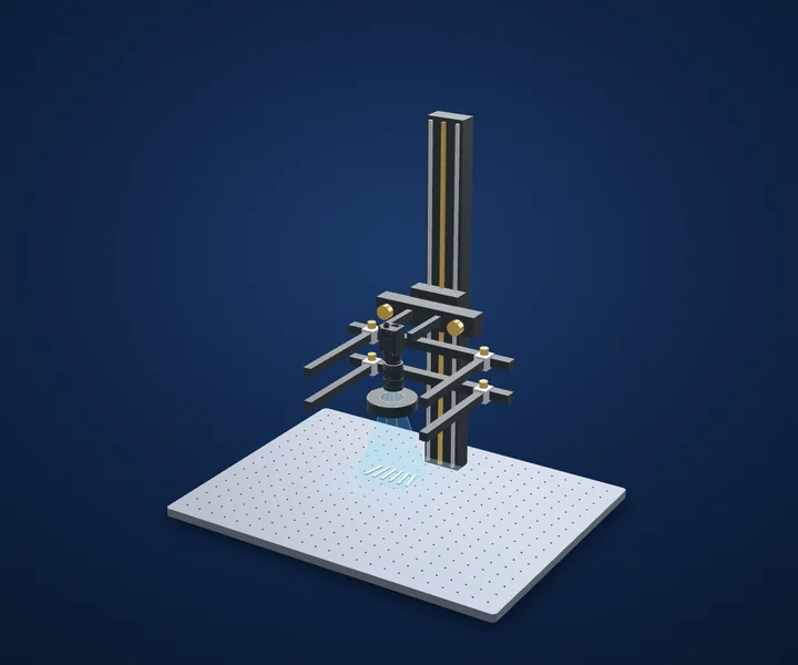
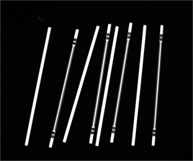
Front and back features on slender metal parts
Base orientation on a repeatable feature, not on brightness alone.
- MethodWhite polarized illumination
- EvidenceReal application-lab capture
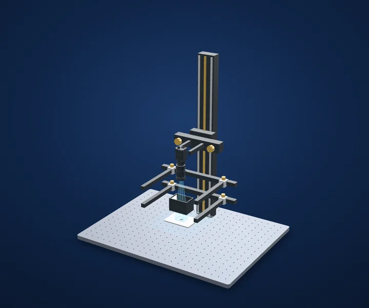
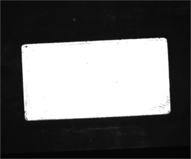
Metal positioning with short-exposure strobe lighting
A short exposure needs a verified light-and-trigger recipe before it becomes a motion-freezing claim.
- MethodStrobe coaxial white light
- EvidenceReal application-lab capture
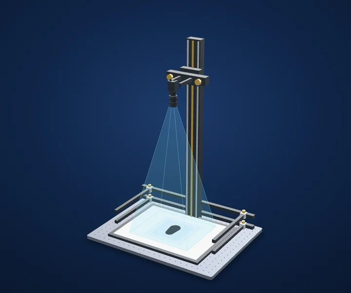
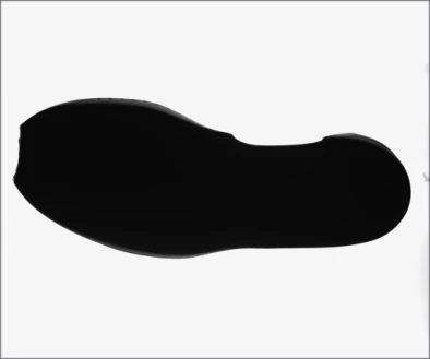
Insole outline and cut shape
Control flexible-part shape before comparing the cut outline.
- MethodTransmitted white backlight
- EvidenceReal application-lab capture
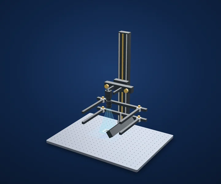

Dot-printed date-code contrast
Keep dots separate in the image before evaluating a date reader.
- Light in sourceLS-2BS23738-RGBW · blue
- EvidenceReal application-lab image
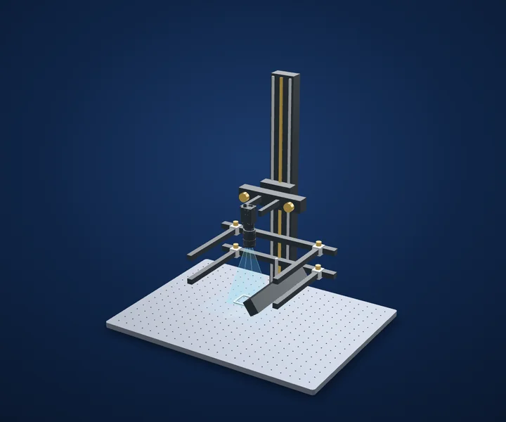
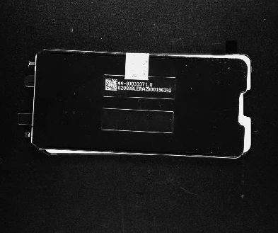
Serial-code imaging on a dark cover
Make the mark repeatable in the image before measuring traceability performance.
- Light in sourceLS-2BS23738-RGBW · white
- EvidenceReal application-lab image
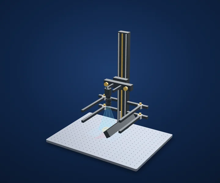
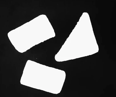
Bread-piece outline and orientation
A usable outline is the first step; prove the handling task on real product variation.
- Light in sourceLS-2BS28238-RGBW · red
- EvidenceReal application-lab image
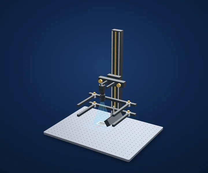
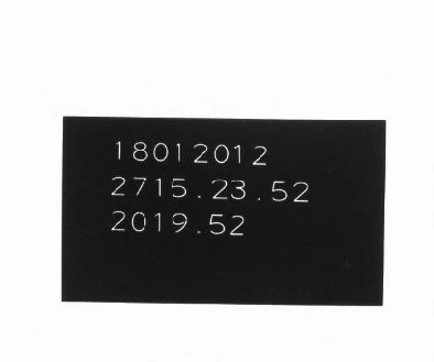
Light-on-dark characters on paper
Match the reader to the actual print polarity before judging recognition performance.
- Light in sourceLS-2BS14738-RGBW · red
- EvidenceReal application-lab image
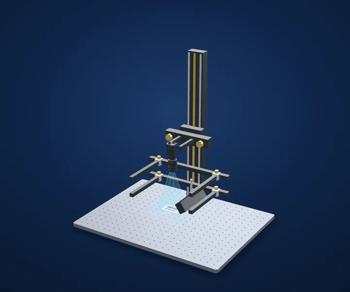
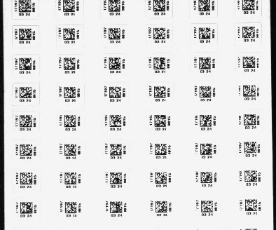
Two-dimensional codes on repeated labels
Choose how many labels fit the field from the smallest code module, not the sheet size.
- Light in sourceLS-2BS14738-RGBW · white
- EvidenceReal application-lab image
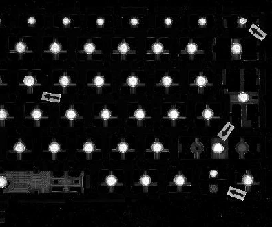
Repeated contacts on a keyboard mat
Use the visible contact pattern to test orientation; verify switch function independently.
- Light in sourceLS-2BD23738-RGBW · blue
- EvidenceReal application-lab image
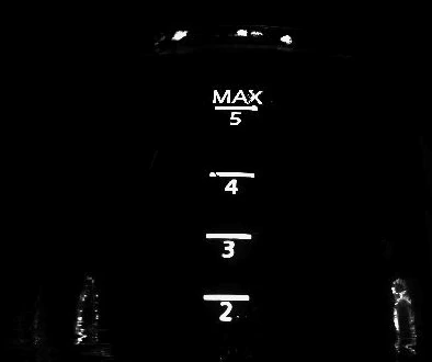
Graduated scale character contrast
A clear scale image is not itself a calibrated measurement.
- Light in sourceLS-2BD14738-RGBW · white
- EvidenceReal application-lab image
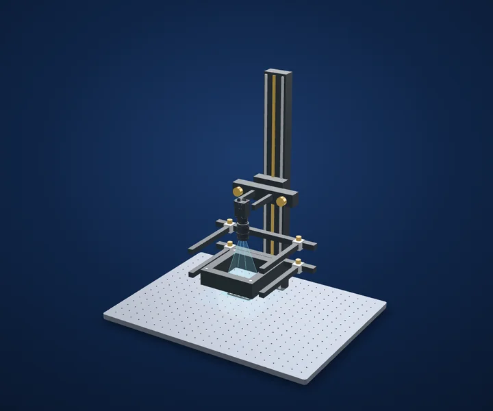
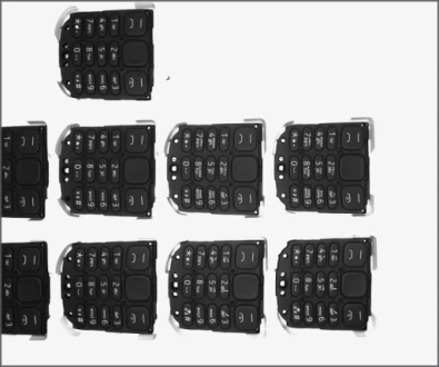
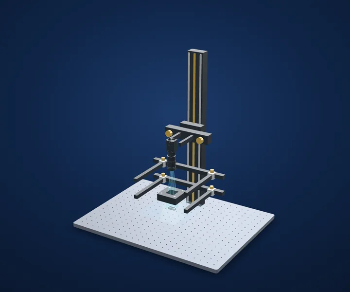
Printed legends on moulded keypads
Choose the lighting direction for the printed stroke, not just the key outline.
- Light in sourceLS-ROS154 · white
- EvidenceReal application-lab image
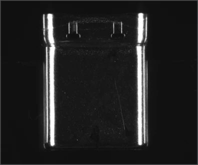
Surface appearance on USB shells
Control the reflection before deciding which surface lines are defects.
- Light in sourceLS-ROS78 · white
- EvidenceReal application-lab image
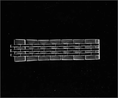
Surface appearance across bracelet links
Use accepted finish variation to stop normal link reflections becoming defects.
- Light in sourceLS-ROS154 · white
- EvidenceReal application-lab image
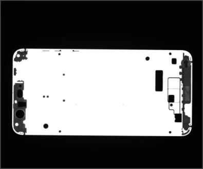
Phone-frame contour positioning
Use stable geometry for position; validate the machine-coordinate result separately.
- Light in sourceLS-ROS154 · white
- EvidenceReal application-lab image
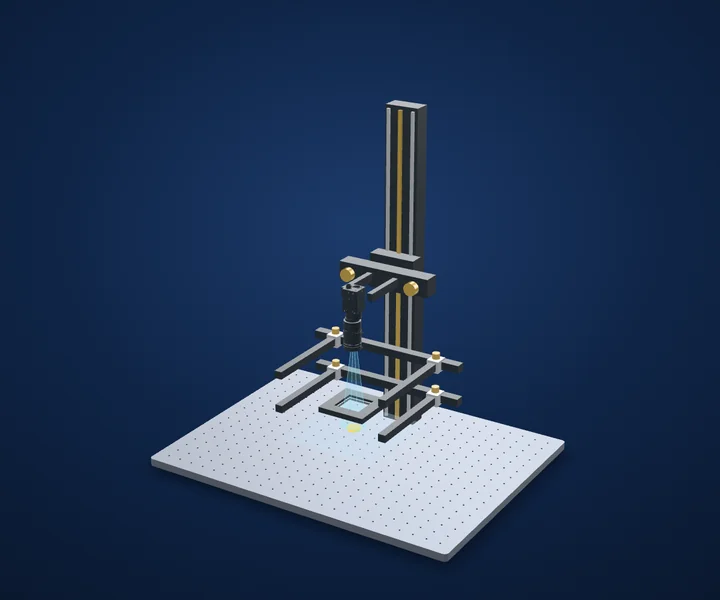
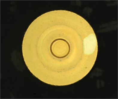
Colour appearance on a bottle cap
Control the colour recipe before turning a lighter patch into a reject decision.
- Light in sourceLS-FCS50 · white
- EvidenceReal application-lab image
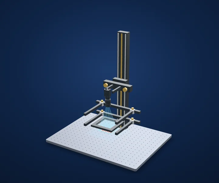
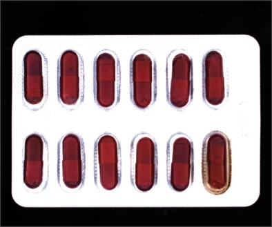
Powder appearance around capsule pockets
Inspect the pocket surroundings, and validate any leak conclusion by the required method.
- Light in sourceLS-FCS100 · white
- EvidenceReal application-lab image
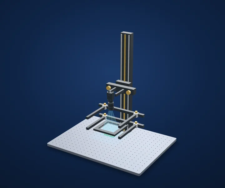
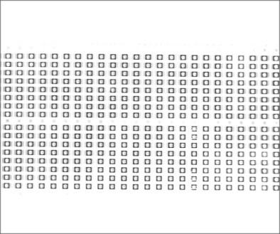
LED-panel and substrate appearance
Use the pattern for appearance checks and verify device function independently.
- Light in sourceLS-FCS100 · white
- EvidenceReal application-lab image
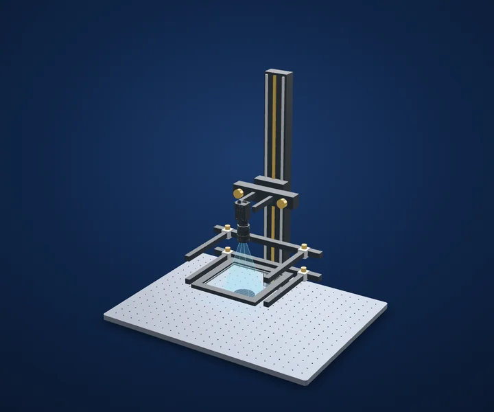
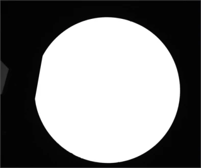
Wafer edge and flat-segment positioning
Use the visible edge geometry, then prove the coordinate accuracy on the actual wafer.
- Light in sourceLS-FCS150 · white
- EvidenceReal application-lab image
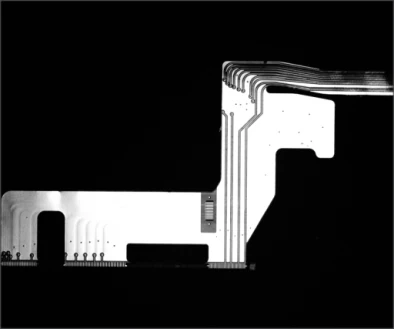
Flexible-circuit shape positioning
Fixture the flex before trusting its projected position.
- Light in sourceLS-FCS200 · blue
- EvidenceReal application-lab image
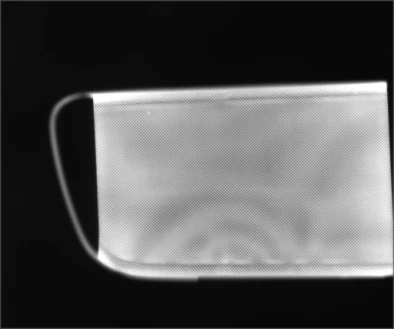
Reflective mirror-surface appearance
Prove a local defect signal before interpreting a reflected brightness pattern.
- Light in sourceLS-FCS150 · white
- EvidenceReal application-lab image
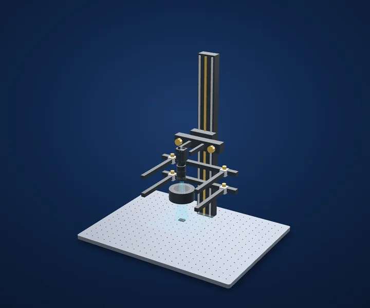
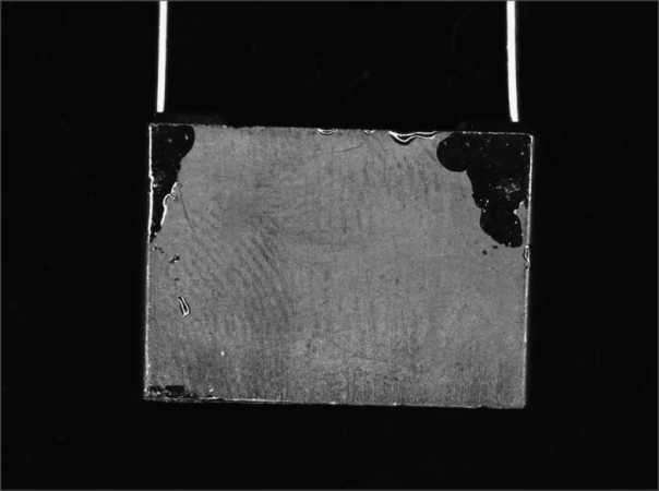
Resin appearance on a leaded component
First identify the material regions, then validate the appearance rule.
- Light in sourceLS-FRS88 · white
- EvidenceReal application-lab image
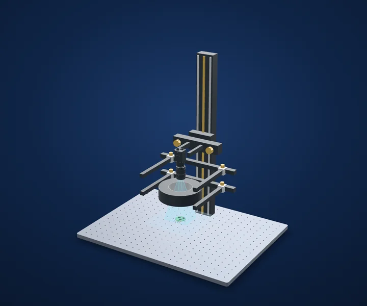
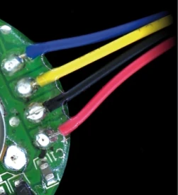
Wire-colour appearance at PCB joints
Use colour to inspect the visible assignment and test the electrical connection separately.
- Light in sourceLS-FRS150 · white
- EvidenceReal application-lab image
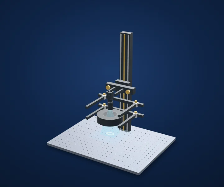
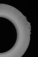
Outer-rim damage on a plastic loop
Agree which rim changes are unacceptable before assigning an edge threshold.
- Light in sourceLS-FRS150 · white
- EvidenceReal application-lab image
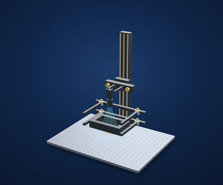
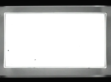
Carton outlines under rectangular shadowless light
Locate the package from a defined contour rather than its printed graphics.
- Proposed light housing (spec)200 × 116 × 42 mm
- EvidenceReal application-lab captures
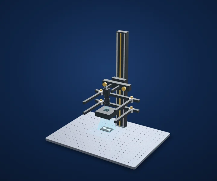
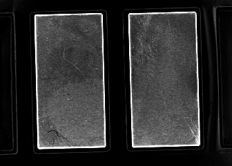
Metal insert outlines in a dark carrier
A clear metal outline is the start of a measurement trial, not its accuracy result.
- Proposed light housing (spec)96 × 96 × 30 mm
- EvidenceReal application-lab captures
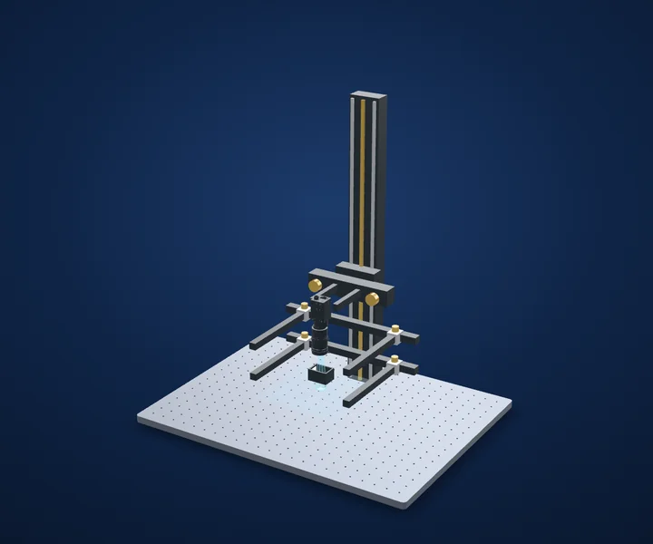
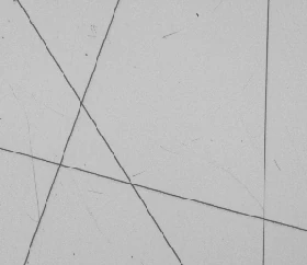
Phone-shell scratches under precision coaxial light
Control the reflected field before setting a scratch threshold.
- Proposed light housing (spec)41 × 30 × 24 mm
- EvidenceReal application-lab captures
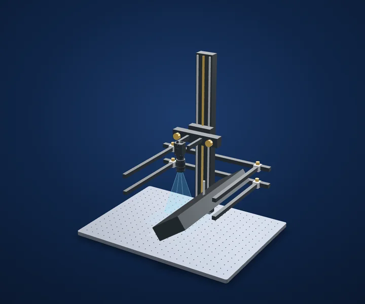
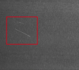
Scratch contrast on a machined cylinder
A curved surface needs a tested angular coverage plan.
- Proposed light housing (spec)440 × 50 × 117.13 mm
- EvidenceReal application-lab captures
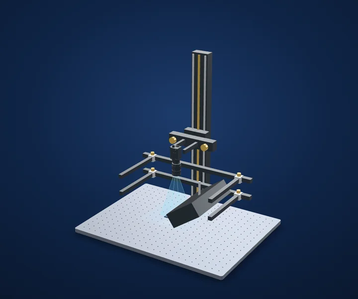
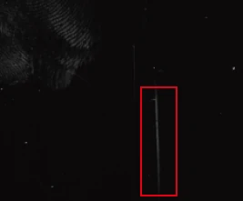
Three line-light trials on display glass
Choose a lighting direction on your screen before comparing light output.
- Proposed light housing (spec)220 × 53 × 121.5 mm
- EvidenceReal application-lab captures
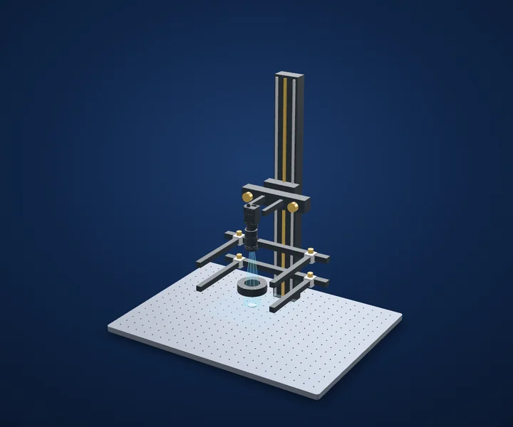
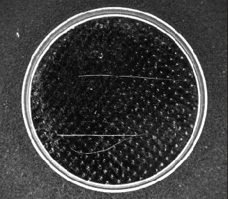
Metal-surface contrast with a high-power strobe ring
Turn extra light into a verified exposure budget, not an assumed speed claim.
- Proposed light housing (spec)Ø74 × 20 mm
- EvidenceReal application-lab captures
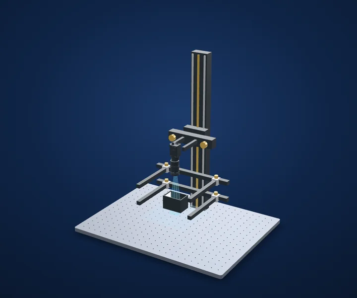
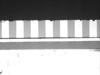
Grid spacing on a glass cover plate
Clear stripes support measurement only after the edge rule and scale are proven.
- Proposed light housing (spec)74 × 50 × 50 mm
- EvidenceReal application-lab captures
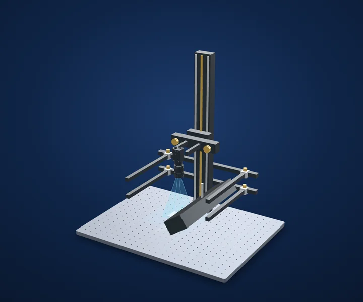
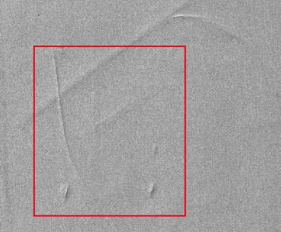
Indentation marks on aluminium film
Make a surface change visible before deciding whether it exceeds the specification.
- Proposed light housing (spec)340 × 48 × 75 mm
- EvidenceReal application-lab captures
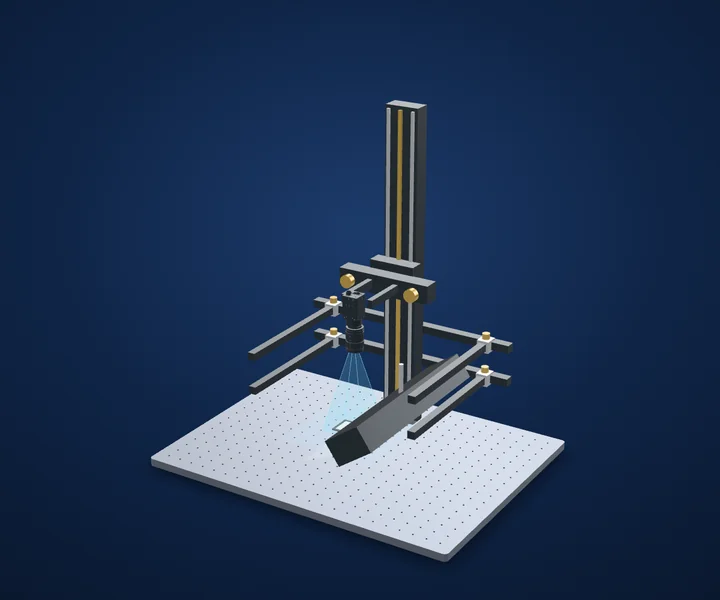
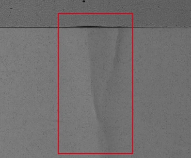
Label creases under an oblique line light
Choose a light angle that separates a crease from normal label features.
- Proposed light housing (spec)340 × 48 × 75 mm
- EvidenceReal application-lab captures
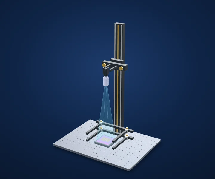
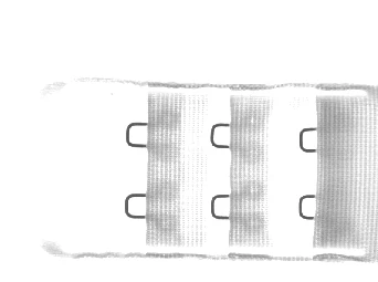
Fastener loops beneath fabric in infrared
Choose wavelength from the actual textile and hardware combination.
- Proposed light housing (spec)114 × 114 × 17 mm
- EvidenceReal application-lab captures
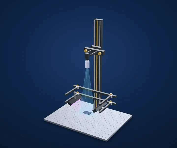
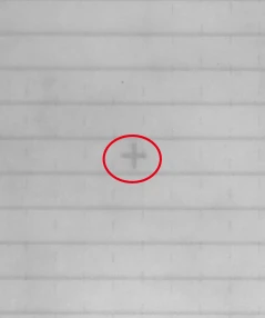
Photovoltaic reference marks at1300 nm
Choose the spectral band for the mark you need to locate.
- Proposed light housing (spec)162 × 22 × 36 mm
- EvidenceReal application-lab captures
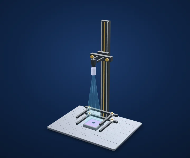
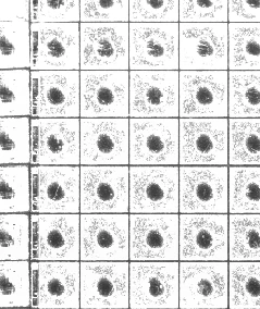
Repeated wafer features in SWIR
Validate the sample material before generalizing a spectral result.
- Proposed light housing (spec)117 × 117 × 23 mm
- EvidenceReal application-lab captures
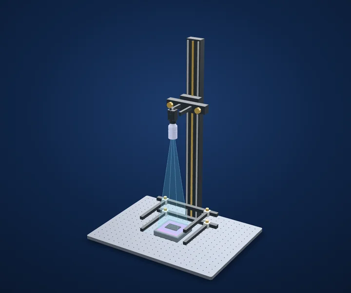
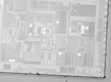
Chip circuit detail at1300 nm
Revealing structure is a prerequisite, not a hidden-defect result.
- Proposed light housing (spec)117 × 117 × 23 mm
- EvidenceReal application-lab captures
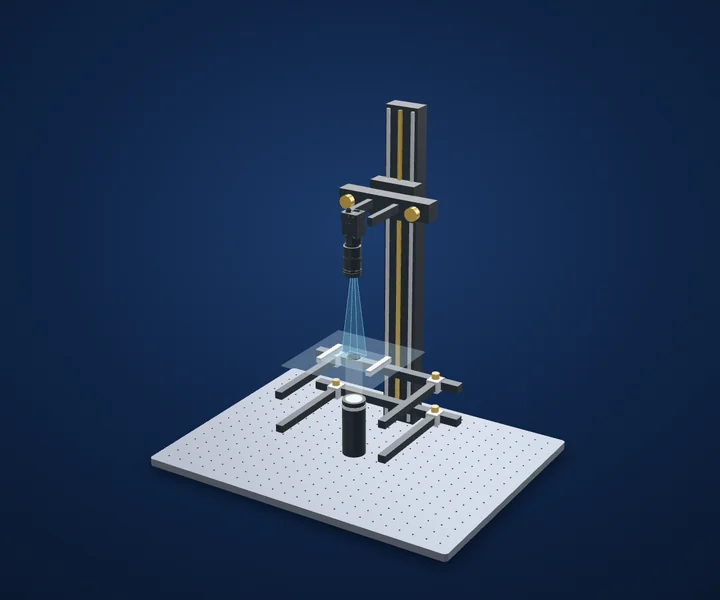
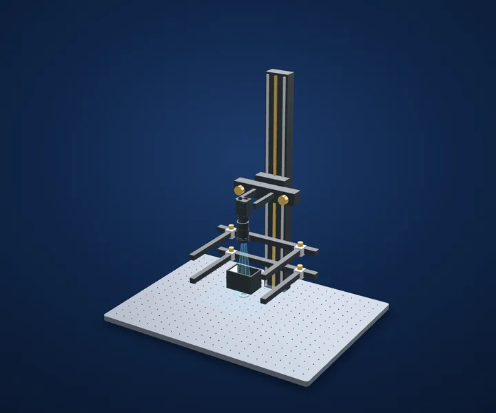
Round-part diameter silhouette
A reported accuracy needs a reproducible measurement method.
- Proposed light housing (spec)Ø42 × 105 mm
- EvidenceReal application-lab captures
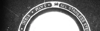
Engraved characters on a metal watch rim
Character visibility must be followed by a measured reading trial.
- Proposed light housing (spec)74 × 50 × 50 mm
- EvidenceReal application-lab captures
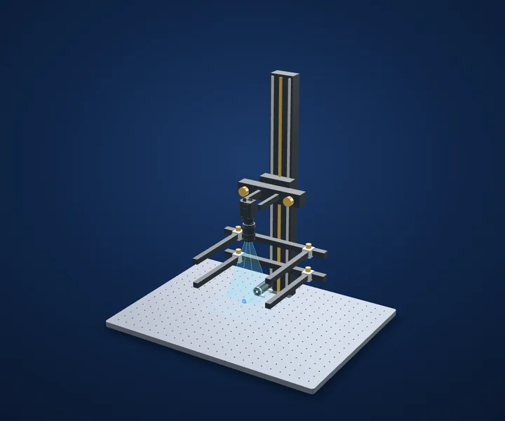
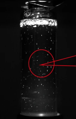
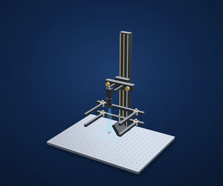
Visible features in a vial under end illumination
Separate a bright-feature image from a verified particle decision.
- Proposed light housing (spec)Ø24 × 62 mm
- EvidenceReal application-lab captures
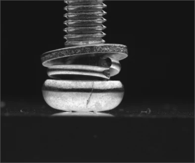
Crack appearance on a fastener head
Keep the head face visible, then distinguish damage from normal head features.
- Light in sourceLS-HFS5050 · white
- EvidenceReal application-lab image
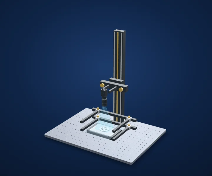
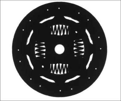
Spring-window appearance in a clutch plate
Use the spring-window pattern for appearance and prove mechanical function separately.
- Light in sourceLS-HFS150100 · white
- EvidenceReal application-lab image
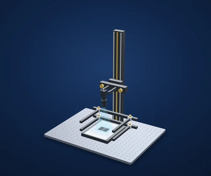
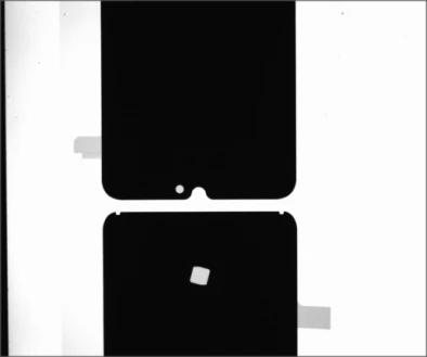
Punched holes and notches in film
Choose sampling for the smallest cut-out, then control the film plane.
- Light in sourceLS-HFS200150 · white
- EvidenceReal application-lab image
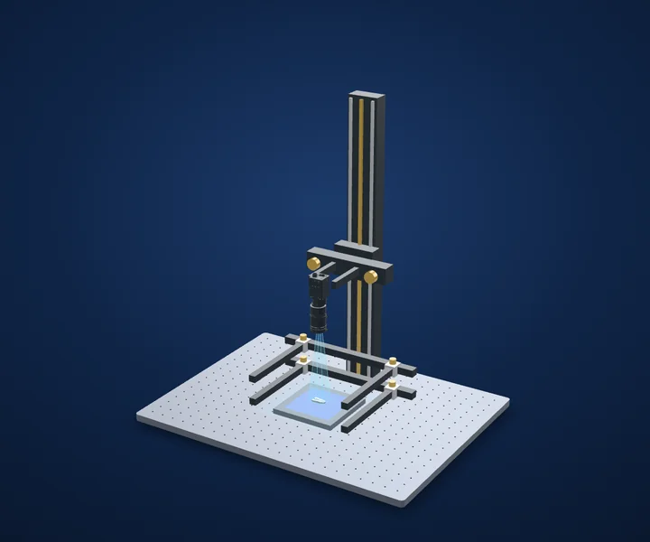
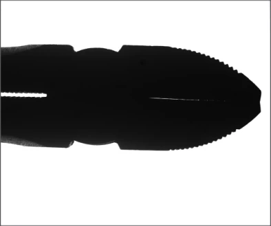
Narrow-gap appearance between plier jaws
Prove the narrow light path before claiming a gap measurement.
- Light in sourceLS-2FS100100 · blue
- EvidenceReal application-lab image
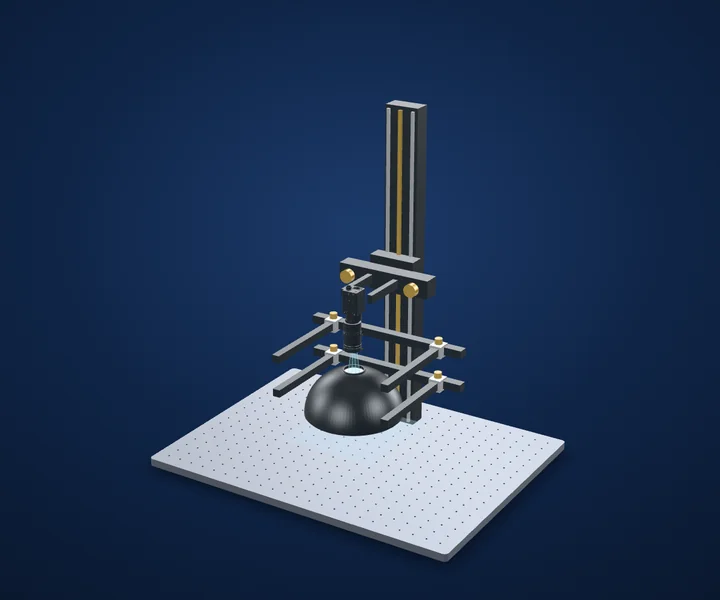
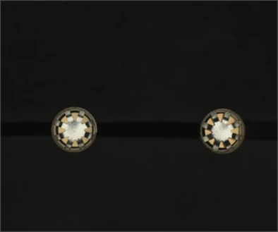
Reflective fuse-terminal appearance
Use diffuse light for terminal appearance and test electrical performance separately.
- Light in sourceLS-DS175 · white
- EvidenceReal application-lab image
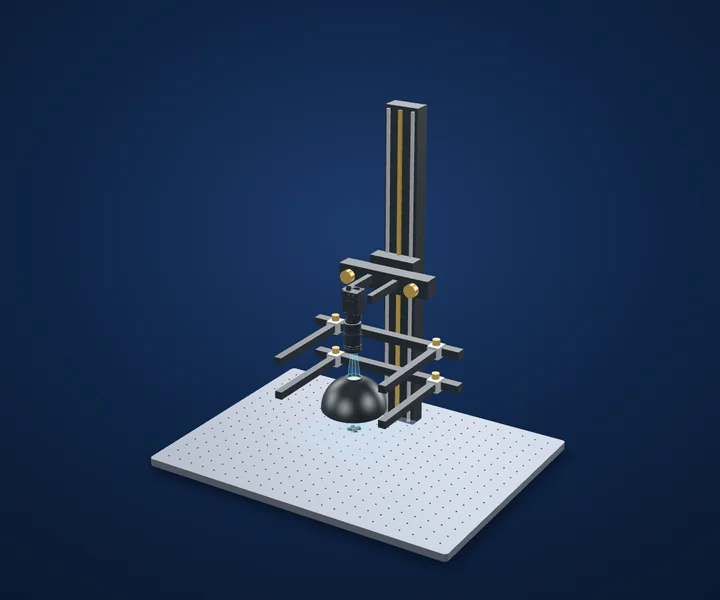
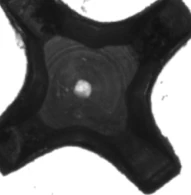
Appearance inside a recessed centre
Build the clean-recess reference before assigning bright regions to contamination.
- Light in sourceLS-DS116 · white
- EvidenceReal application-lab image
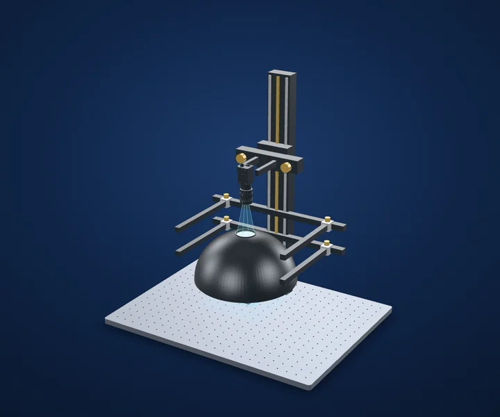
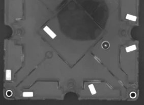
Visible insert regions in a moulded carrier
Verify what each visible region represents before using it as an assembly rule.
- Light in sourceLS-DS260 · white
- EvidenceReal application-lab image
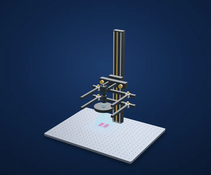
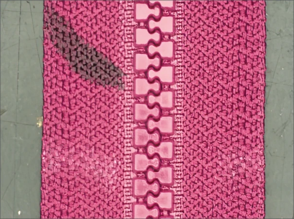
Interlocking zipper-tooth appearance
Inspect the tooth pattern against real fabric variation before testing a defect rule.
- Light in sourceLS-FLS116 · white
- EvidenceReal application-lab image
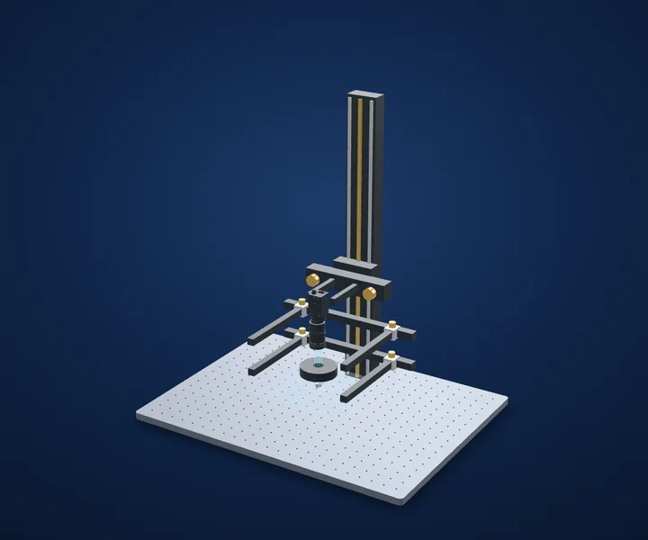
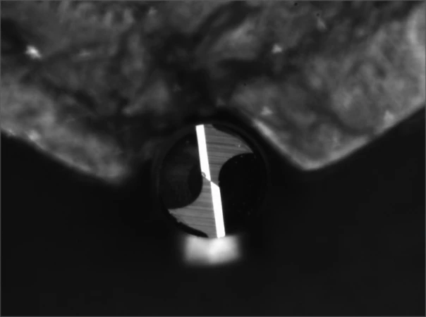
Cutting-bit end-face appearance
Prove the local end-face signal before assigning a wear or damage threshold.
- Light in sourceLS-FLS74 · blue
- EvidenceReal application-lab image
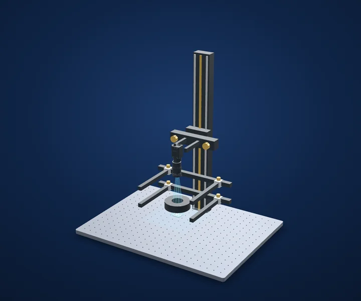
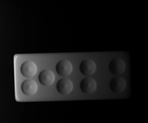
Four-zone imaging of recessed circular features
Preserve directional evidence before choosing how to combine it.
- Proposed light housing (spec)Ø91 × 25.5 mm
- EvidenceReal application-lab captures
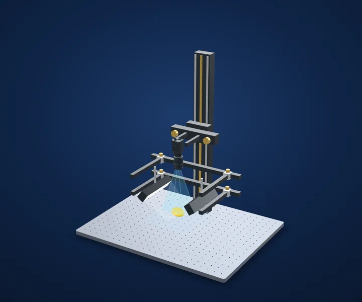
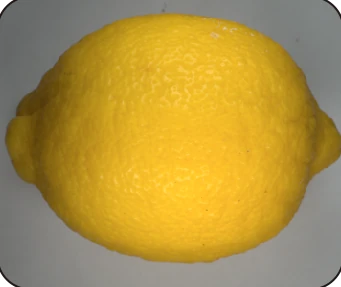
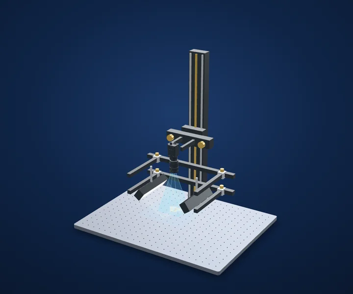
Fruit colour under two source lighting conditions
A colour threshold needs controlled capture and a defined reference.
- Proposed light housing (spec)162 × 36 × 26 mm
- EvidenceReal application-lab captures
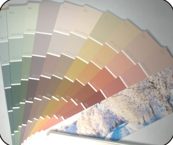
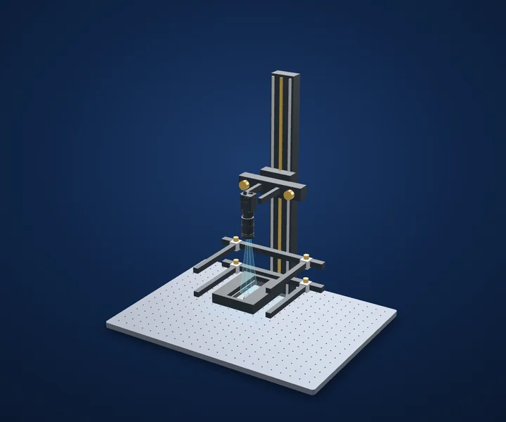
Material swatches under two lighting conditions
Compare the material against a controlled reference, not a changing capture setup.
- Proposed light housing (spec)162 × 36 × 26 mm
- EvidenceReal application-lab captures
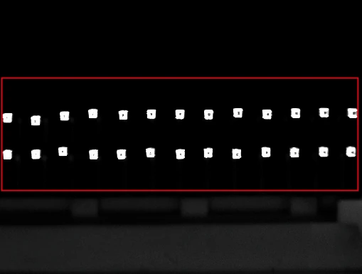
Pin-tip location with selective illumination
Select a useful tip signal before asking software to locate it.
- Proposed light housing (spec)120 × 150 × 26 mm
- EvidenceReal application-lab captures
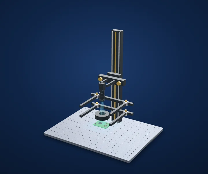
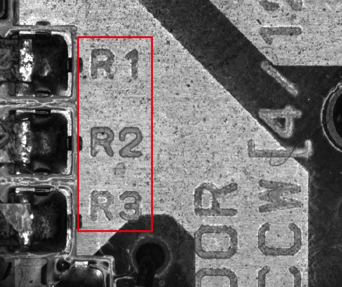
Printed PCB reference markings under diffuse ring light
A readable-looking mark needs a measured character-verification trial.
- Proposed light housing (spec)Ø91 × 25.5 mm
- EvidenceReal application-lab captures
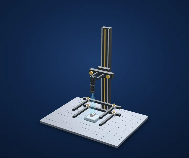
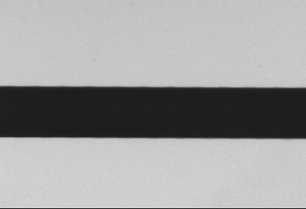
Metal-column edges under two backlights
Choose the backlight for edge stability rather than brightness alone.
- Proposed light housing (spec)84 × 84 × 19 mm
- EvidenceReal application-lab captures
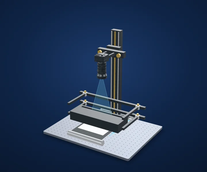
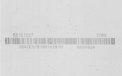
Barcode contrast under coaxial line lights
Preserve the barcode structure before claiming a short-exposure reading result.
- Source exposure35 µs on all four captures
- Proposed acquired line2048 pixels
No applications match. Try another term or select All applications.
Don't see your application? Describe your part in a quote request of Systeem configureren stap voor stap.