
Screw thread pitch: a telecentric test reporting less than 0.007 mm
The application-lab sheet reports less than 0.007 mm over a 19.34 × 16.21 mm field using a bi-telecentric lens and collimated backlight. The useful design lesson is how the optics produce a stable, high-contrast thread silhouette.
Stabilize scale and edge contrast before judging a tolerance.
- Campo de visão19.34 × 16.21 mm
- Image2456 × 2058 px
- Accuracy (as tested)< 0.007 mm
- Distância de trabalho73 mm
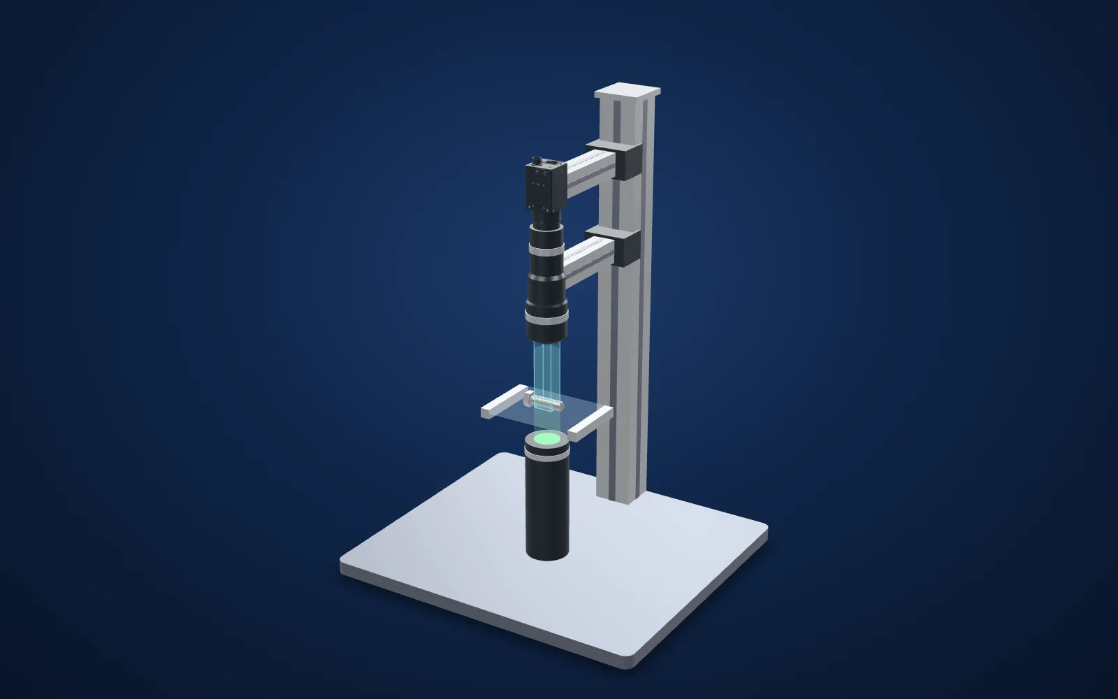 Drag to rotate · scroll to zoom
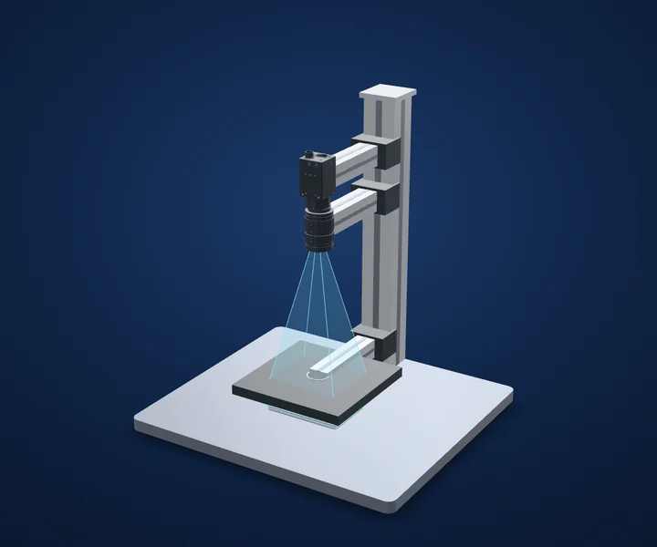
Camera and CAD lens geometry are published models where available. Light housings use printed dimensions; fixtures, parts, beam shapes and spacing illustrate the inspection principle. This is not an optical simulation or a dimensioned installation drawing.
Evidence you can inspect
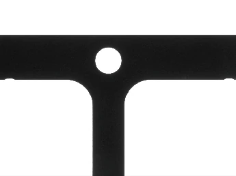
The source camera capture shows the thread as a high-contrast silhouette.
<0.007 mm over 19.34 × 16.21 mm, at 2456 × 2058 pixels, as stated on the source sheet.
A reported application-lab result. It is not a guaranteed tolerance for the proposed camera or a production measurement study.
What the camera saw
Cropped from the source test sheet; original test annotations are retained. Captures are not generated or enhanced. Drag the comparison slider or use the image buttons.
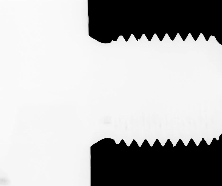
The challenge
Pitch, crest and root measurements need edges that do not move when the screw sits a little higher or lower in the fixture. With a standard lens, a part that is closer looks bigger, and the flanks of a thread blur where they leave the focal plane.
Front lighting makes it worse: the machined flanks reflect unevenly, so the edge the software finds depends on surface finish rather than geometry.
How it was solved
The test identifies the LS-VCM230-26 bi-telecentric lens and a green collimated backlight from the LS-VCL-26 family. Its source camera is 5 MP with a 2/3-inch sensor; the camera below is a current proposed alternative, not the source camera.
The lens reduces magnification changes with object distance, while the backlight puts the thread edges against a bright field. The reported field and image width correspond to approximately 7.9 µm per pixel (19.34 mm / 2456 px).
Why it works
- 1
Telecentric optics reduce perspective and scale changes within their specified operating range. Calibration and part alignment still matter.
- 2
Collimated backlighting limits edge wraparound and provides a useful silhouette for edge-based measurements.
- 3
The source reports <0.007 mm but gives no uncertainty budget, repeatability sample or edge-fitting method. Pixel sampling alone does not establish measurement accuracy.
What to validate on your part
A useful sample image is the starting point. These are the checks that turn the concept into a defensible inspection.
- 01
Establish scale
Calibrate with a traceable artefact at the actual part plane and aperture.
- 02
Check repeatability
Repeat loading, rotate the part and vary height within the required fixture range.
- 03
Budget uncertainty
Include calibration, edge extraction, pose, thermal drift and part variation.
The set-up and the parts
| Camera (test) | 5 MP, 2/3", 3.45 µm pixels |
|---|---|
| Lente | Bi-telecentric, 0.438x, C-mount |
| Luz | Collimated (telecentric) backlight, green |
| Distância de trabalho | 73 ± 1 mm (lens spec) |
| Profundidade de campo | ± 2.3 mm @ F11 (lens spec) |
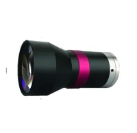
Bi-telecentric, 0.438x, made for 2/3" sensors.
$999.00In proposed setup
Collimated light matched to the lens's 26 mm field; the test used the green version.
$289.00In proposed setup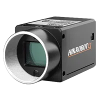
Same sensor format as the test camera: 5 MP, 2/3", 3.45 µm, monochrome (2448 × 2048 px).
$819.00In proposed setup"Tested" identifies the part named in the source. "Our pick" is a proposed alternative or supporting part. The quote includes only cards marked "In proposed setup", with the quantities shown; other test arrangements are separate. Confirm colour, optics, controllers, power supplies, cables and mounting before ordering.
About this case study: the photos and camera images come from the application laboratory of the maker of the lighting and optics we sell, imaged on the parts shown; your results depend on your part, camera and set-up. This is an application-lab study, not a LumaSpec customer deployment. Source figures are reported results; proposed components require a fresh trial. The 3D scene illustrates the arrangement and does not simulate imaging performance.
More case studies
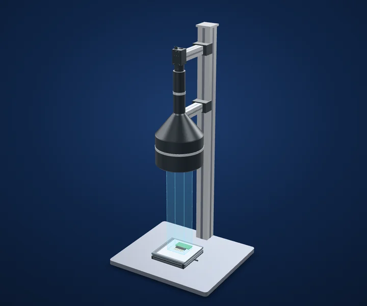
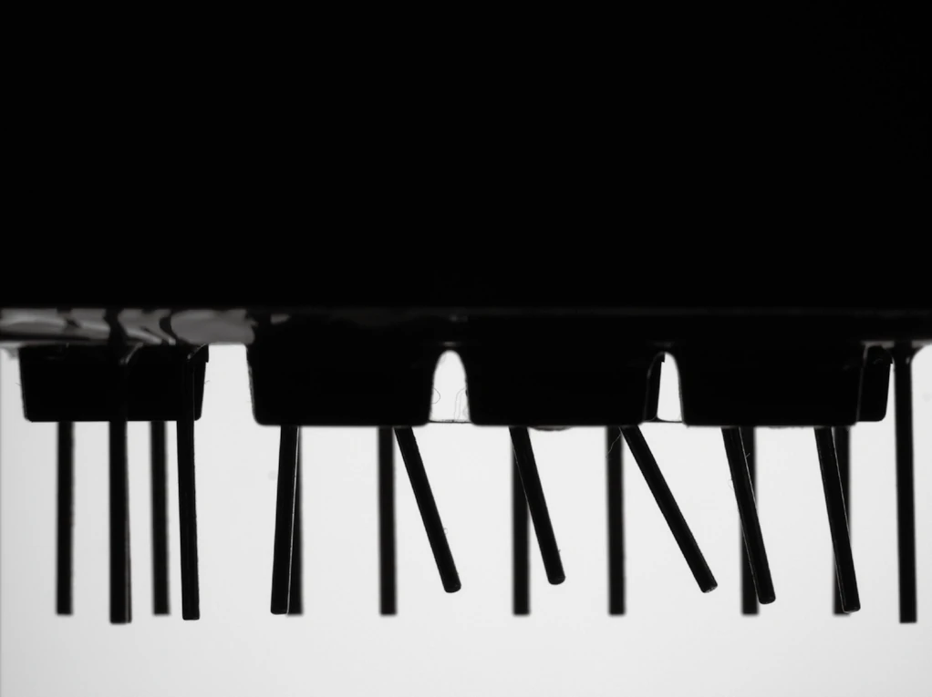
Bent pins on connectors and boards
Separate real pin lean from perspective.
- Campo de visão50.46 × 37.85 mm
- Image2592 × 1944 px
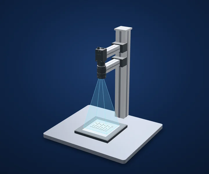
Stamped-metal terminal contours
Use a silhouette when the requirement is shape.
- Test lightWhite thin-panel backlight
- Housing (spec)140 × 140 × 9.5 mm
Battery welds and tabs
Control what shiny metal reflects.
- LuzFlat dome, 100 × 100 mm emitting
- Tamanho140 × 140 × 11.5 mm
Make the next trial specific.
Tell us the part size, smallest defect or tolerance, available working distance, material and line speed. Include what a good part and a reject look like.
Discuss your applicationConfigurar um sistema