
Seeing bruises under the skin: NIR vs SWIR on apples
Two supplied images of the same apple compare 940 nm near-infrared and 1550 nm short-wave infrared. The 1550 nm capture shows stronger dark patches at the marked bruises, illustrating why wavelength choice matters.
Match the wavelength, sensor and optics as one system.
- NIR940 nm
- SWIR1550 nm
- KameraInGaAs, 900–1700 nm
- ResultBruises dark and wide at 1550 nm
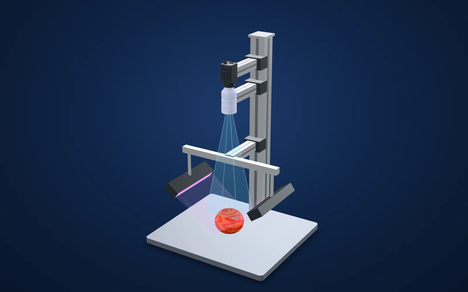 Drag to rotate · scroll to zoom
Camera and CAD lens geometry are published models where available. Light housings use printed dimensions; fixtures, parts, beam shapes and spacing illustrate the inspection principle. This is not an optical simulation or a dimensioned installation drawing.
Evidence you can inspect
The annotated 1550 nm image shows two dark regions more distinctly than the 940 nm image.
The sheet labels the wavelengths as 940 nm and 1550 nm; it supplies no sorting accuracy or bruise-depth data.
One illustrated sample. Confirm contrast across your fruit varieties, ripeness and damage ages.
What the camera saw
Cropped from the source test sheet; original test annotations are retained. Captures are not generated or enhanced. Drag the comparison slider or use the image buttons.
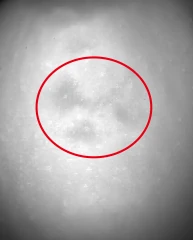
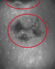 NIR 940 nmSWIR 1550 nm
SWIR 1550 nm: SWIR 1550 nm: two dark bruises with clear borders (marked by the tester).
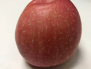
The challenge
The colour photograph shows little obvious surface damage. The inspection problem is to find damage that has weak visible contrast.
Near-infrared at 940 nm goes a little deeper and shows one soft area, but the contrast is low and the second bruise is missed.
How it was solved
Changing wavelength changes the relative absorption and scattering of light in the fruit. This application compares 940 nm with 1550 nm; tissue and moisture differences can affect that contrast.
The test imaged the same apple at 940 nm and at 1550 nm. At 1550 nm both bruises show as dark patches with clear borders, including one at the top that the 940 nm image misses.
Why it works
- 1
The supplied 1550 nm capture shows stronger bruise contrast on this apple. Cultivar, maturity and time since damage need separate validation.
- 2
The proposed SWIR camera and lens cover the required band. A standard visible-only camera cannot be assumed to work at 1550 nm.
- 3
The purple light paths in the 3D scene are a visual convention for invisible infrared; they do not depict a visible purple source or measured penetration.
What to validate on your part
A useful sample image is the starting point. These are the checks that turn the concept into a defensible inspection.
- 01
Cover real variation
Test varieties, ripeness, surface moisture and different times after damage.
- 02
Match the complete spectral path
Verify the light wavelength, lens transmission, filters and sensor response together.
- 03
Check movement
Set exposure and trigger timing using fruit moving at the intended conveyor speed.
The set-up and the parts
| Beleuchtung | SWIR LED light, 1550 nm (and 940 nm for comparison) |
|---|---|
| Kamera | InGaAs SWIR area scan |
| Objektiv | SWIR-corrected, 900–1700 nm |

Ring light from the same SWIR series as the test (seven wavelengths, 1050 to 1650 nm); ask for 1550 nm. 90 mm outside, 40 mm inside.
$149.00Separate test / alternative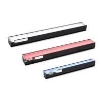
Same series as a bar, for a line of fruit on a conveyor; two bars light both sides.
$389.00In proposed setup · quantity 2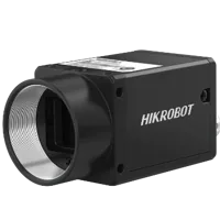
1.3 MP InGaAs SWIR camera (Sony IMX990, 5 µm pixels), C-mount, fanless.
Preis auf AnfrageIn proposed setup
25 mm F1.4 lens corrected for 900–1700 nm.
$449.00In proposed setup"Tested" identifies the part named in the source. "Our pick" is a proposed alternative or supporting part. The quote includes only cards marked "In proposed setup", with the quantities shown; other test arrangements are separate. Confirm colour, optics, controllers, power supplies, cables and mounting before ordering.
About this case study: the photos and camera images come from the application laboratory of the maker of the lighting and optics we sell, imaged on the parts shown; your results depend on your part, camera and set-up. This is an application-lab study, not a LumaSpec customer deployment. Source figures are reported results; proposed components require a fresh trial. The 3D scene illustrates the arrangement and does not simulate imaging performance.
More case studies
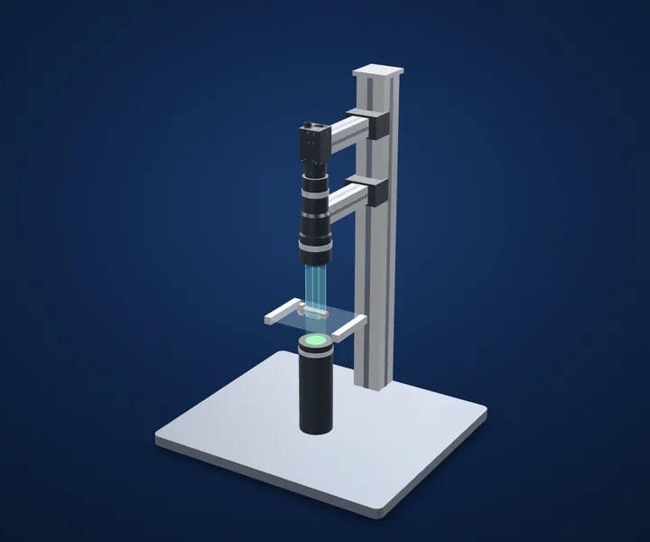
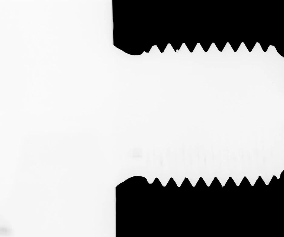
Screw thread pitch with telecentric optics
Stabilize scale and edge contrast before judging a tolerance.
- Sichtfeld19.34 × 16.21 mm
- Image2456 × 2058 px
Bent pins on connectors and boards
Separate real pin lean from perspective.
- Sichtfeld50.46 × 37.85 mm
- Image2592 × 1944 px
Battery welds and tabs
Control what shiny metal reflects.
- BeleuchtungFlat dome, 100 × 100 mm emitting
- Größe140 × 140 × 11.5 mm
Make the next trial specific.
Tell us the part size, smallest defect or tolerance, available working distance, material and line speed. Include what a good part and a reject look like.
Discuss your applicationSystem konfigurieren