
 MV-CL024-91GMView part & specifications →Browse camera options →
Início / Case studies / Barcode contrast under coaxial line lights
Application study · Reflective identifiers and traceabilityReflective barcode imaging: compare four lights at a source-reported 35 µs
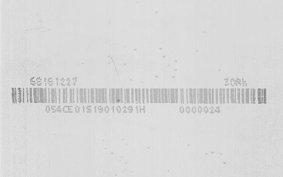
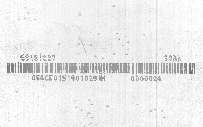
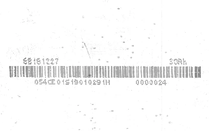
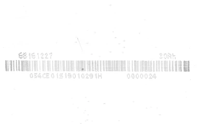
Four real captures show the same printed barcode/serial region under four coaxial line lights, each labelled 35 µs exposure. Their different brightness and bar contrast make a useful exposure-budget comparison without claiming a successful decode or transport speed.
Preserve the barcode structure before claiming a short-exposure reading result.
- Source exposure35 µs on all four captures
- Proposed acquired line2048 pixels
- Proposed line field (derived)183.8 mm at the printed lens pair
- Source acquisitionCamera/motion not identified
Test stationIncluded light holdersCâmeraLenteIluminaçãoPartAcquired lineMaterial travel · external transport
 Drag to rotate · scroll to zoom
Walk through this setup 5 guided stops
From component to inspection
Understand each choice.
Choose a stop to frame the part in 3D and see why it belongs in this setup. The component notes and links remain available if 3D cannot load.
Proposed component
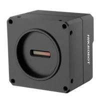
MV-CL024-91GM
GigE monochrome line camera with 2048 × 7 µm pixels and external line triggering. This is a proposed replacement for an unspecified source camera.
Proposed component
LS-AF2524M-M42
25 mm, 29 mm image circle, M42 × 1 and 12 mm flange back. Printed magnification is 0.078x at 300 mm WD.
Tested component
LS-4COXL300
White source light selected as the proposed trial starting point. Printed 340 × 56 × 115 mm envelope;294 × 15 mm viewport and 300 × 24 mm emitting area. It is not claimed to be the best light for every code.
Proposed component
LS-BT-XZ-G-6-6045
600 mm column, 600 × 450 mm breadboard, glass tray and two lighting holders. Proposed bench fixture; actual load, travel, clamps, mounting fasteners and light clearance must be confirmed.
Inspect the real capture
Follow the contrast to the part.
Preserve the barcode structure before claiming a short-exposure reading result.
Camera and available lens CAD are published models. The light drawing gives the 340 × 56 × 115 mm body and 294 × 15 mm viewing port. The off-centre port, rotated housing and clear acquired line are shown; internal source and 45-degree optics are schematic. The acquired line is not a full area-camera frame. Part shape, unencoded 3D bars, transport, brackets and spacing are illustrative; no source conveyor or actual barcode payload is reproduced. Confirm optical/mechanical clearance, light drive and trigger timing. Light paths are not an optical simulation.
From the demo to your test benchCâmeraMV-CL024-91GMView part & specifications →Browse camera options → Imaging lens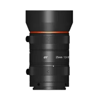 LS-AF2524M-M42View part & specifications →Browse imaging lens options →
Inspection light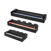 LS-4COXL300View part & specifications →Browse inspection light options →
Test station & mounts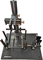 LS-BT-XZ-G-6-6045View part & specifications →Browse test station & mounts options →
Build around the parts you can buy.
Explore each component, check its specifications and compare alternatives. The proposed quote includes the linked test station; its catalog listing includes two lighting holders.
MV-CL024-91GMView part & specifications →Browse camera options →LS-AF2524M-M42View part & specifications →Browse imaging lens options →LS-4COXL300View part & specifications →Browse inspection light options →LS-BT-XZ-G-6-6045View part & specifications →Browse test station & mounts options →Mount the optics with intent
The station is an optical test bench, with its two lighting holders included in the catalog listing. The 3D column and base follow the published height and footprint. Carriages, clamps and part supports are schematic: confirm camera screw pattern, lens support, light fasteners, permissible load and actual travel before ordering.
Configure the mounting station →Complete the electrical system
Select a controller against the exact light voltage, drive mode and power, then confirm camera data/power/I/O cables and a suitable PC. These are not silently added to the proposed optical kit.
Lighting application-lab image sheet
Evidence you can inspect
Visible in the images
The four captures have different background brightness and barcode/serial contrast at the labelled 35 µs exposure.
What the source reports
The source states 35 µs for all four named lights but gives no source camera, transport speed, line rate or decoder result.
How to use this evidence
An application-lab lighting demonstration, not a customer deployment or a qualified production inspection. Proposed camera, lens, fixture and scene spacing require a fresh trial. Source observations do not establish a defect-size limit, accuracy guarantee or production false-call rate.
What the camera saw
Cropped from the source test sheet; original test annotations are retained. Captures are not generated or enhanced. Drag the comparison slider or use the image buttons.
The challenge
A reflective surface can lose the narrow bars in a weak signal or a bright background. A reliable reader needs preserved modules, margins and contrast at the required exposure.
How it was solved
The source names white LS-4COXL300, LS-4COHL300, LS-3COHL300 and LS-4COSL300. Each frame explicitly states 35 µs; its source camera and acquisition mode are not identified.
The proposed system uses a 2048-pixel line-scan camera and a matched M42 lens. It is a new moving-material concept, not evidence that the original test used line-scan acquisition. The illustrative transport is external to the quoted optical kit.
Why it works
- 1
Coaxial line illumination aligns a concentrated bright field with a narrow inspection region. Enough light can support short exposure, but excessive brightness can also weaken the visible print contrast.
- 2
Exposure time alone does not establish a line rate, conveyor speed or decoding performance. The proposed line rate must be calculated from the required field, sampling and motion, then verified on real codes.
From image contrast to a production decision
What to validate on your part
A useful sample image is the starting point. These are the checks that turn the concept into a defensible inspection.
- 01
Check real code quality
Include the required symbology, module width, quiet zones and acceptable print variation.
- 02
Budget motion and line rate
Calculate sampling, encoder triggering and permitted pixel travel using the actual transport speed.
- 03
Validate decoding
Test correct reads, no-reads and substitutions over representative reflective finishes at the chosen light and exposure settings.
Engineer the motion requirement
What line rate does your application need?
A planning calculation for the proposed 2048-pixel camera. Change the inspected width and transport speed to see square-pixel sampling. These are calculated requirements, not measured test results.
Across-web sampling
Required line rate
Exposure for 1 px travel
Sampling = width / 2048; line rate = speed / sampling.
The exposure value allows one pixel of motion blur; a stricter blur budget needs a shorter exposure. Verify light output, defect contrast, encoder timing, camera limits and network/PC capacity. Changing width requires revisiting lens magnification and working distance.
The set-up and the parts
| Source exposure | 35 µs, as printed on each source capture |
|---|---|
| Source camera/acquisition | Not identified; no source line rate or speed given |
| Proposed camera | MV-CL024-91GM · 2048-pixel line scan |
| Proposed lens/field | LS-AF2524M-M42 · printed 0.078x at 300 mm WD; derived 183.8 mm line field |
| Mounting (proposed) | LS-BT-XZ-G-6-6045 · test station; external transport must be specified |
IluminaçãoTestedLS-4COXL300
White source light selected as the proposed trial starting point. Printed 340 × 56 × 115 mm envelope;294 × 15 mm viewport and 300 × 24 mm emitting area. It is not claimed to be the best light for every code.
$729.00In proposed setup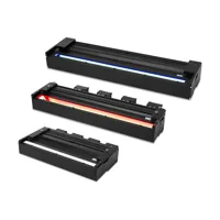
IluminaçãoTestedLS-4COHL300
White light in the same 35 µs source comparison.
$729.00Separate test / alternative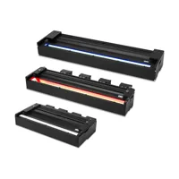
IluminaçãoTestedLS-3COHL300
White light in the same 35 µs source comparison.
$659.00Separate test / alternative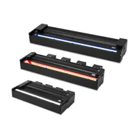
IluminaçãoTestedLS-4COSL300
White light in the same 35 µs source comparison.
$729.00Separate test / alternativeCâmeraOur pickMV-CL024-91GM
GigE monochrome line camera with 2048 × 7 µm pixels and external line triggering. This is a proposed replacement for an unspecified source camera.
$1,209.00In proposed setupLenteOur pickLS-AF2524M-M42
25 mm, 29 mm image circle, M42 × 1 and 12 mm flange back. Printed magnification is 0.078x at 300 mm WD.
$639.00In proposed setupCamera test stationOur pickLS-BT-XZ-G-6-6045
600 mm column, 600 × 450 mm breadboard, glass tray and two lighting holders. Proposed bench fixture; actual load, travel, clamps, mounting fasteners and light clearance must be confirmed.
$359.00In proposed setup"Tested" identifies the part named in the source. "Our pick" is a proposed alternative or supporting part. The quote includes only cards marked "In proposed setup", with the quantities shown; other test arrangements are separate. Confirm colour, optics, controllers, power supplies, cables and mounting before ordering.
About this case study: the photos and camera images come from the application laboratory of the maker of the lighting and optics we sell, imaged on the parts shown; your results depend on your part, camera and set-up. This is an application-lab study, not a LumaSpec customer deployment. Source figures are reported results; proposed components require a fresh trial. The 3D scene illustrates the arrangement and does not simulate imaging performance.
More case studies
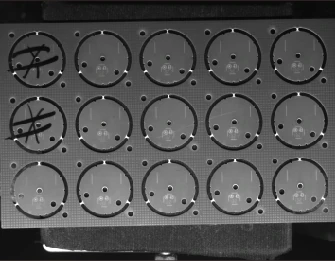
Electronics manufacturing · PCB surface inspection
Even light across repeated PCB panels
A repeated feature needs repeatable illumination wherever it lands.
- Proposed light housing (spec)196 × 20.3 × 27 mm
- EvidenceReal lighting-lab captures
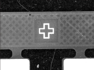
Electronics manufacturing · Fiducial location
Bright PCB fiducial on a textured background
A visible fiducial becomes a positioning tool only after calibration and repeatability checks.
- Proposed light housing (spec)Ø50 × 17.5 mm
- EvidenceReal lighting-lab captures
Connectors and electronics · Contact-feature inspection
Repeated connector contacts under coaxial light
Start with a clear image of the observable contact geometry.
- Proposed light housing (spec)74 × 50 × 50 mm
- EvidenceReal lighting-lab captures
Start with your inspection requirement
Make the next trial specific.
Tell us the part size, smallest defect or tolerance, available working distance, material and line speed. Include what a good part and a reject look like.
Discuss your applicationConfigurar um sistema