
Component faces: find dirt on inductors and capacitors under white ring lights
Two source images show the top faces of small components under white ring lights. A square grey inductor face carries a brown smear near one corner, and a white capacitor face shows a small dark double speck near its edge.
Light each face evenly and judge dirt against the clean texture of that part type.
 Manufacturer test image
- Lights in sourceLS-RNG-0798 · LS-RNG-0807, white
- EvidenceManufacturer test image
- Imaging kitCamera, lens and fixture proposed
- AcceptanceValidate on representative parts
Explore it in 3D

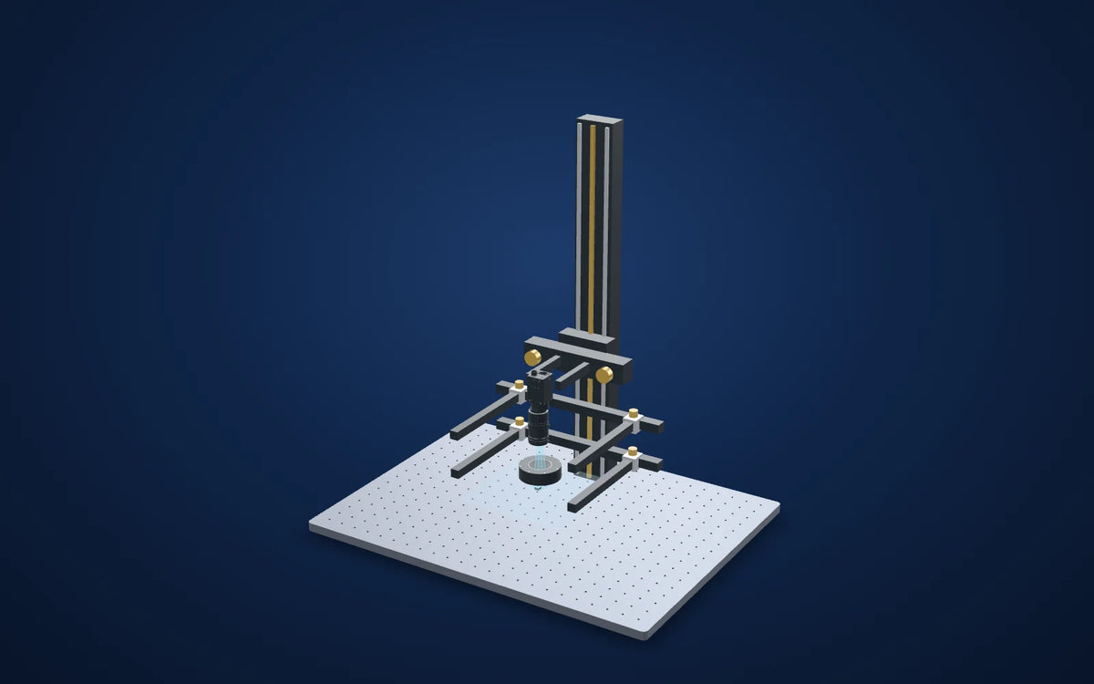
Camera and available lens CAD are published models. Lens and light envelopes use printed dimensions. The linked station uses its published base size and column height; carriage, brackets, fittings, parts and spacing are illustrative. Confirm load, travel, fasteners and clearances before ordering. Light paths explain the arrangement and do not simulate optical performance. Representative part geometry is illustrative, not reconstructed inspection evidence. The specimen and lighting distance are representative, not dimensions or settings recovered from the source capture.
Lighting manufacturer's application test image
What the camera saw
Images from the manufacturer's application test, cropped; the original annotations are kept and nothing is generated or enhanced. Drag a comparison slider, or open any image full size.
The challenge
Component faces are small, and dirt can be a faint smear on a textured grey face or a tiny speck on a bright white one.
A light that suits one face can wash out or hide marks on the other.
How it was solved
The source identifies white ring lights for these examples: 66 mm with a 60° angle for the inductor and 100 mm with a 90° angle for the capacitor face.
Image each face through the ring with the proposed colour camera and flag areas that differ from the clean face texture. The source does not name its camera, lens or software.
Why it works
- 1
A ring close to the part lights the flat face evenly from all round, so a smear or speck changes the brightness locally.
- 2
The two faces need different contrast settings; the source gives no minimum dirt size or detection rate.
Lighting manufacturer's application test image
Evidence you can inspect
The inductor face shows a brown smear near one corner; the capacitor face shows a small dark double speck near its edge.
The source captions the examples as inductor dirt inspection and capacitor surface dirt inspection and identifies the two white ring lights.
Two source captures of different parts. No part size, minimum dirt size or detection rate is supplied.
From image contrast to a production decision
What to validate on your part
- 01
Seed real contaminants
Add flux, grease, dust and marks of the smallest size that must be rejected on each part type.
- 02
Include normal texture
Image clean parts with their full moulding and surface variation before setting limits.
- 03
Set limits per part type
Keep separate exposure and contrast settings for dark and bright faces.
From the demo to your test bench
Parts in this setup
 LightTested
LS-RNG-0798
66 mm dia. ring light, 60° (LS-RNG-0798)
White version of the 66 mm, 60° ring light identified with the inductor image. Printed OD 66 × ID 35 × H 20 mm. The catalog lists red, green, blue and white variants; this trial selects white.
$199.00
In proposed setup
Alternative light (second image)Tested
LS-RNG-0807
100 mm dia. ring light, 90° (LS-RNG-0807)
White version of the 100 mm, 90° ring light identified with the capacitor-face image. Printed OD 100 × ID 40 × H 18 mm. Shown for reference; not in the proposed quote.
$269.00
Separate test / alternative
 CameraOur pick
MV-CS050-10GC
Hikrobot MV-CS050-10GC 5MP Area Scan Camera, GigE, IMX264, Color, Basic
5 MP colour global-shutter camera proposed because the source capture is in colour. Confirm white balance, exposure and colour processing on the actual parts.Not available in the United States. Available for delivery to other countries.
$739.00
In proposed setup
 LensOur pick
LS-FFL-1456
35 mm, F2.8, 1.1", C-mount, Macro lens (59 mm (-0.7X) to 150 mm (-0.25X)) (LS-FFL-1456)
Proposed 35 mm C-mount macro lens at its printed 0.5x magnification / 78 mm working-distance pair. The proposed 2448 × 2048 sensor with 3.45 µm pixels gives a derived 16.8912 × 14.1312 mm field; confirm focus, coverage and residual distortion on the real sample. The illustrated field holds both small faces only for the scene; the source images each part on its own.
$339.00
In proposed setup
 Camera test stationOur pick
LS-MNT-0097
Camera stand with XZ adjustment and glass tray, height 600 mm, 600 x 450 mm base (LS-MNT-0097)
600 mm column, 600 × 450 mm breadboard, XZ adjustment, glass tray and two lighting holders as listed. Proposed bench fixture; confirm loads, travel and camera/lens clamps.
$1,309.00
In proposed setup
"Tested" marks the part the manufacturer used in its application test. "Our pick" is our proposed alternative or supporting part, not tested by the manufacturer in this set-up. Confirm colour, optics, controllers, power supplies, cables and mounting before ordering.
The set-up
| Tested lights | LS-RNG-0798 (inductor) and LS-RNG-0807 (capacitor face), white |
|---|---|
| Source camera / lens | Not specified in the source image caption; proposed parts below |
| Proposed lens point | 0.5x at 78 mm, printed lens pair |
| Derived proposed field | 16.8912 × 14.1312 mm = sensor dimensions / 0.5x; not a source test field |
| Ring envelope (printed) | OD 66 × ID 35 × H 20 mm, 60° (inductor image) |
| Second image light (printed) | LS-RNG-0807: OD 100 × ID 40 × H 18 mm, 90° |
| Mounting (proposed) | LS-MNT-0097; 600 mm column, 600 × 450 mm base, glass tray and two included lighting holders |
Mount the optics with intent
The station is an optical test bench, with its two lighting holders included in the catalog listing. The 3D column and base follow the published height and footprint. Carriages, clamps and part supports are schematic: confirm camera screw pattern, lens support, light fasteners, permissible load and actual travel before ordering.
Complete the electrical system
Select a controller against the exact light voltage, drive mode and power, then confirm camera data/power/I/O cables and a suitable PC. These are not silently added to the proposed optical kit.
Build this system
Start from this setup, adapt it to your part.
The configurator opens with this study's camera, lens, light and station picked. Swap any part, check fit and price, then buy or ask for a quote.
Camera and available lens CAD are published models. Lens and light envelopes use printed dimensions. The linked station uses its published base size and column height; carriage, brackets, fittings, parts and spacing are illustrative. Confirm load, travel, fasteners and clearances before ordering. Light paths explain the arrangement and do not simulate optical performance. Representative part geometry is illustrative, not reconstructed inspection evidence. The specimen and lighting distance are representative, not dimensions or settings recovered from the source capture.
Electronics and devices
Related case studies

 Electronics and devices
Bent pins on connectors and boards
Separate real pin lean from perspective.Field of view50.46 × 37.85 mmExplore the study

 Electronics and devices
Black-painted metal under a flat dome
Make the reflected field consistent before calling a surface defect.Proposed light housing (spec)140 × 140 × 11.5 mmExplore the study

 Electronics and devices
Buzzer polarity mark
Find the round outline first, then use the mark for rotation.Light in sourceLS-CXL-0124 · blueExplore the study
Make the next trial specific.
Tell us the part size, smallest defect or tolerance, available working distance, material and line speed. Include what a good part and a reject look like.
About this case study: the photos and camera images are the manufacturer's application test images, supplied by the maker of the tested part and taken on the parts shown; LumaSpec did not run this test. Your results depend on your part, camera and set-up. This is a manufacturer's application study, not a LumaSpec customer deployment. Reported figures are the manufacturer's; proposed components require a fresh trial. The 3D scene illustrates the arrangement and does not simulate imaging performance.