
PCB hole pattern and outline gauging: a telecentric worked example
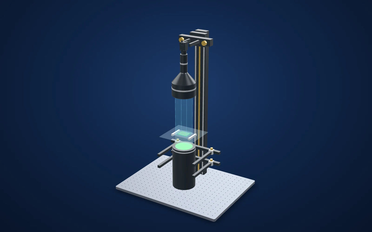
A worked example, not a customer project: a 0.127x bi-telecentric lens over a 90 mm collimated backlight shows a small bare board's through-holes as bright dots and its outline as a dark edge, so hole positions can be gauged against the outline. Every number is calculated from the parts' printed rows.
Backlight the holes and let the telecentric lens hold the scale; check copper features in a separate view.
- Field of view (derived)About 66.5 × 55.6 mm
- Sampling (derived)About 27.2 µm per pixel
- Working distance (lens spec)208 ± 3 mm
- Depth of field (lens spec)± 27.2 mm @ F11
Explore it in 3D

Camera CAD is the published model. Lens and light envelopes use printed dimensions. The linked station uses its published base size and column height; carriage, brackets, fittings, the part and spacing are illustrative. Confirm load, travel, fasteners and clearances before ordering. Light paths explain the arrangement and do not simulate optical performance. The part is a generic example, not a real customer part.
The challenge
Hole position checks on a bare board compare drilled holes with the board outline and with each other. Under front light, copper, solder mask and silkscreen all compete with the hole edges.
A board that bows or sits on a carrier changes height across the field; with a conventional lens that height change also changes the scale towards the edges of the image.
How it was solved
The LS-TCL-2693 prints 0.127x, 208 ± 3 mm working distance, ± 27.2 mm depth of field at F11 and a 90 mm object field. With the MV-CS050-10GM(NPOE) sensor of about 8.45 × 7.07 mm the field is about 66.5 × 55.6 mm, which takes a board of about 56 × 44 mm in one image with room for placement.
The LS-CLM-0079 is the lens's printed matching light: a 90 mm collimated beam, which covers the field diagonal of about 86.7 mm, and a 69-139 mm light working distance. Light shining up through the holes makes them bright on the dark board.
Why it works
- 1
Sampling is about 3.45 µm / 0.127 = 27.2 µm per pixel, so a 1.0 mm hole spans about 37 pixels and a 3.2 mm mounting hole about 118. Hole centres are fitted from many edge points, but their uncertainty still has to be measured on the real system.
- 2
Bi-telecentric optics keep the scale nearly constant through the printed depth of field, which matters for a board that is not perfectly flat.
- 3
The silhouette ignores solder mask colour and silkscreen. It does not show copper, pad or annular-ring defects; those need front light.
Worked application example (calculated, no test image)
Evidence you can inspect
No camera image is shown. This is a worked example built from catalog rows, not a test of a real part.
Nothing is reported as measured. Field, sampling and light coverage are calculated from the lens's printed magnification, working distance and depth of field, the camera's printed pixel count and pixel size, and the light's printed beam diameter.
The numbers describe what the optics sample, not a measurement uncertainty or a detection limit. Run a trial and a measurement study with real parts before relying on any tolerance.
From image contrast to a production decision
What to validate on your part
- 01
Calibrate the scale
Use a traceable dot or grid plate at the board plane and record aperture and light current.
- 02
Test flatness and placement
Repeat with bowed and flat boards and with the board shifted across the field.
- 03
Compare with a reference
Measure the same boards on a coordinate measuring machine and assess bias and repeatability against the hole-position limits.
From the demo to your test bench
Parts in this setup
 Bi-telecentric lensOur pick
LS-TCL-2693
Bi-telecentric lens for 2/3" cameras, 0.127x, WD 208 mm, C-mount (LS-TCL-2693)
0.127x, 208 ± 3 mm working distance, ± 27.2 mm @ F11 depth of field and an 11.4 mm maximum sensor size, as printed.
$2,889.00
In proposed setup
 Collimated lightOur pick
LS-CLM-0079
Collimated (telecentric) illumination, beam dia. 90 mm, length 223.9 mm (LS-CLM-0079)
Printed 90 mm beam (covers the field diagonal of about 86.7 mm) and 69-139 mm light working distance. Green shown; red, blue and white versions are listed.
$1,059.00
In proposed setup
 CameraOur pick
MV-CS050-10GM(NPOE)
Hikrobot MV-CS050-10GM(NPOE) 5 MP GigE area scan camera, IMX264, Gen 2 basic version, Mono, Without PoE
Monochrome C-mount camera, 2448 × 2048 px of 3.45 µm (printed); its sensor diagonal of about 11.0 mm is within the lens's 11.4 mm limit.Not available in the United States. Available for delivery to other countries.
$819.00
In proposed setup
 Camera test stationOur pick
LS-MNT-0101
Camera stand with XZ adjustment and glass tray, height 800 mm, 600 x 450 mm base (LS-MNT-0101)
800 mm column, 600 × 450 mm breadboard, XZ adjustment, glass tray and two lighting holders as listed. Proposed bench fixture; confirm loads, travel and camera/lens clamps.
$1,329.00
In proposed setup
"Tested" marks the part the manufacturer used in its application test. "Our pick" is our proposed alternative or supporting part, not tested by the manufacturer in this set-up. Confirm colour, optics, controllers, power supplies, cables and mounting before ordering.
The set-up
| Lens | LS-TCL-2693 · bi-telecentric · 0.127x · C-mount |
|---|---|
| Light | LS-CLM-0079 · collimated · 90 mm beam |
| Camera | MV-CS050-10GM(NPOE) · 2448 × 2048 px · 3.45 µm |
| Working distance | 208 ± 3 mm (lens spec) |
| Field of view (derived) | About 66.5 × 55.6 mm: 2448 × 2048 px × 3.45 µm / 0.127x |
| Mounting (proposed) | LS-MNT-0101 · camera test station with glass tray and two lighting holders |
Mount the optics with intent
The station is an optical test bench, with its two lighting holders included in the catalog listing. The 3D column and base follow the published height and footprint. Carriages, clamps and part supports are schematic: confirm camera screw pattern, lens support, light fasteners, permissible load and actual travel before ordering.
Complete the electrical system
This collimated light prints DC 3 V with 350 mA operating current at 1 W and 750 mA at 3 W (1000 mA maximum): it needs a constant-current driver set to those values. Confirm current, colour, connector and power before selecting a controller; a general 24 V voltage controller is not a substitute. Camera cables and PC are separate selections.
Build this system
Start from this setup, adapt it to your part.
The configurator opens with this study's camera, lens, light and station picked. Swap any part, check fit and price, then buy or ask for a quote.
Camera CAD is the published model. Lens and light envelopes use printed dimensions. The linked station uses its published base size and column height; carriage, brackets, fittings, the part and spacing are illustrative. Confirm load, travel, fasteners and clearances before ordering. Light paths explain the arrangement and do not simulate optical performance. The part is a generic example, not a real customer part.
Electronics and devices
Related case studies

 Electronics and devices
Bent pins on connectors and boards
Separate real pin lean from perspective.Field of view50.46 × 37.85 mmExplore the study

 Electronics and devices
Black-painted metal under a flat dome
Make the reflected field consistent before calling a surface defect.Proposed light housing (spec)140 × 140 × 11.5 mmExplore the study

 Electronics and devices
Buzzer polarity mark
Find the round outline first, then use the mark for rotation.Light in sourceLS-CXL-0124 · blueExplore the study
Make the next trial specific.
Tell us the part size, smallest defect or tolerance, available working distance, material and line speed. Include what a good part and a reject look like.
Worked application example (calculated, no test image): No camera image is shown. This is a worked example built from catalog rows, not a test of a real part. The numbers describe what the optics sample, not a measurement uncertainty or a detection limit. Run a trial and a measurement study with real parts before relying on any tolerance.