
 MV-CL024-91GMView part & specifications →Browse camera options →
Inicio / Case studies / A line-scan station for metal surface scratches
Application study · Metal surfacesLine-scan metal-scratch inspection: light, lens and motion
Start with a real lighting-lab capture, then explore a proposed line-scan station with a GigE camera, M42 lens, angled line light and adjustable test stand. Material motion builds the image one line at a time.
The lighting reveals the feature; synchronized material travel turns the line into a useful image.
- Proposed camera2048 pixels · mono
- Interfaz de lenteM42 × 1 · 12 mm flange
- Light aperture300 × 18 mm
- EvidenceLighting trial; system proposed
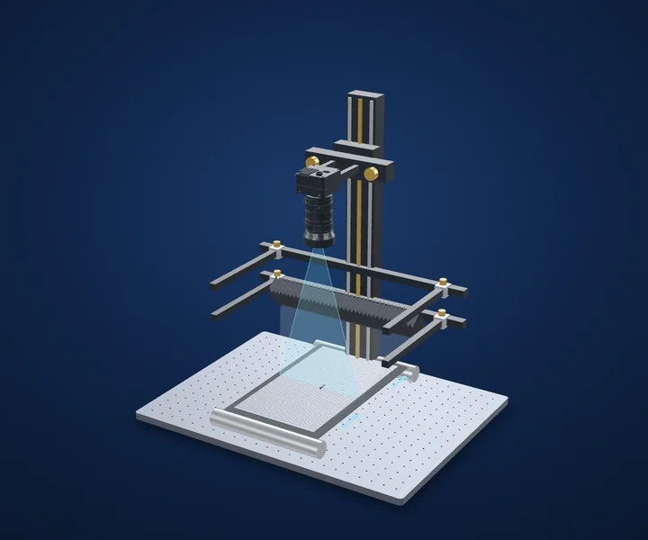
Test stationIncluded light holdersCámaraLenteLuzPartAcquired lineMaterial travel · external transport
 Drag to rotate · scroll to zoom
Walk through this setup 5 guided stops
From component to inspection
Understand each choice.
Choose a stop to frame the part in 3D and see why it belongs in this setup. The component notes and links remain available if 3D cannot load.
Proposed component
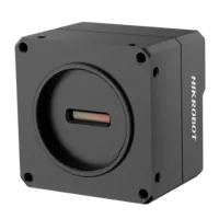
MV-CL024-91GM
GigE monochrome line camera with 2048 × 7 µm pixels and external line triggering. This is a proposed replacement for an unspecified source camera.
Proposed component
LS-AF2524M-M42
25 mm, 29 mm image circle, M42 × 1 and 12 mm flange back. Printed magnification is 0.078x at 300 mm WD.
Tested component
LS-4LINV300
The white light identified on the source application sheet. Adjust angle and intensity on the real surface.
Proposed component
LS-BT-XZ-G-6-6045
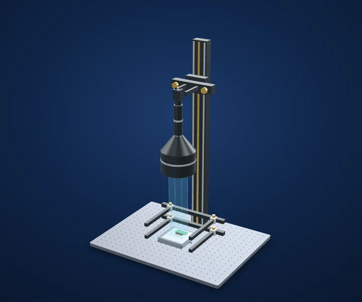
600 mm column, 600 × 450 mm breadboard, XZ adjustment, glass tray and two lighting holders as listed. Proposed bench fixture; confirm loads, travel and camera/lens clamps.
Inspect the real capture
Follow the contrast to the part.
The lighting reveals the feature; synchronized material travel turns the line into a useful image.
Camera and available lens CAD are published models. Lens and light envelopes use printed dimensions. The linked station uses its published base size and column height; carriage, brackets, fittings, parts and spacing are illustrative. Confirm load, travel, fasteners and clearances before ordering. Light paths explain the arrangement and do not simulate optical performance. Rollers and travel arrows represent external motion hardware, which is not included.
From the demo to your test benchCámaraMV-CL024-91GMView part & specifications →Browse camera options → Imaging lens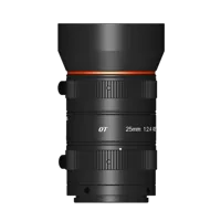 LS-AF2524M-M42View part & specifications →Browse imaging lens options →
Inspection light LS-4LINV300View part & specifications →Browse inspection light options →
Test station & mounts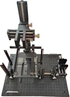 LS-BT-XZ-G-6-6045View part & specifications →Browse test station & mounts options →
Build around the parts you can buy.
Explore each component, check its specifications and compare alternatives. The proposed quote includes the linked test station; its catalog listing includes two lighting holders.
MV-CL024-91GMView part & specifications →Browse camera options →LS-AF2524M-M42View part & specifications →Browse imaging lens options →LS-4LINV300View part & specifications →Browse inspection light options →LS-BT-XZ-G-6-6045View part & specifications →Browse test station & mounts options →Mount the optics with intent
The station is an optical test bench, with its two lighting holders included in the catalog listing. The 3D column and base follow the published height and footprint. Carriages, clamps and part supports are schematic: confirm camera screw pattern, lens support, light fasteners, permissible load and actual travel before ordering. It supports the bench camera and trial light; it is not a conveyor gantry. Production mounting, transport and encoder integration are separate requirements.
Configure the mounting station →Complete the electrical system
Select a controller against the exact light voltage, drive mode and power, then confirm camera data/power/I/O cables and a suitable PC. These are not silently added to the proposed optical kit.
Lighting application-lab capture + proposed line-scan system
Evidence you can inspect
Visible in the images
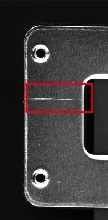
The source capture shows bright scratches on the dark metal cover; the red rectangle is the original test annotation. This crop excludes unrelated printed markings on the cover.
What the source reports
The source attributes the visible surface contrast to the named angled line light. It provides no line rate, transport speed, defect-size threshold or detection statistics.
How to use this evidence
A real lighting application with a proposed line-scan system design. No claim is made that the proposed camera, lens, motion system or processing algorithm produced this capture.
What the camera saw
Cropped from the source test sheet; original test annotations are retained. Captures are not generated or enhanced. Drag the comparison slider or use the image buttons.
The challenge
Scratches on a reflective cover can disappear into the direct reflection. The light angle has to make their scattered light stand out against the surrounding metal.
A line-scan system also has to hold the moving surface at a controlled height and synchronize each acquired line with material travel. A good still image alone does not establish conveyor performance.
How it was solved
The application sheet identifies the white LS-4LINV300 and shows it tilted toward the surface. Its camera, lens, material speed and acquisition mode are not specified. The published image supports the lighting choice, not a claim that our proposed camera was tested.
The proposed Hikrobot MV-CL024-91GM uses 2048 × 7 µm pixels across the line, with GigE output and external line triggering. The LS-AF2524M-M42 lens covers a 29 mm image circle and has the same M42 × 1 mount and 12 mm flange back as the camera.
At the lens table’s 300 mm working distance and 0.078x magnification, the proposed width is about 183.8 mm (14.336 mm sensor length / 0.078). The narrow cyan fan in 3D is the acquired line; the material travels across it. Conveyor, rollers and encoder are illustrative motion requirements, not items in this quote.
Why it works
- 1
An angled line light concentrates illumination across the acquired strip. Its angle changes how the surface sends direct reflections and scattered light into the lens.
- 2
The lens must cover the whole sensor line. This proposal uses a 14.336 mm line and a 29 mm image circle; the matching mount and flange back avoid inserting an arbitrary adapter.
- 3
Cross-web sampling is width / pixels. Along-travel sampling depends on motion per trigger, so an encoder or verified constant-speed synchronization is needed before interpreting image dimensions.
From image contrast to a production decision
What to validate on your part
A useful sample image is the starting point. These are the checks that turn the concept into a defensible inspection.
- 01
Prove surface contrast
Test the worst acceptable surface and the smallest reject at multiple orientations and across the full illuminated width.
- 02
Synchronize the image
Set the line trigger from measured travel; verify the encoder ratio, camera input levels, line pitch and conveyor speed changes.
- 03
Close the throughput budget
Check exposure, light output, camera line rate and network/PC bandwidth together. Include dark-field noise, vibration and focus variation.
Engineer the motion requirement
What line rate does your application need?
A planning calculation for the proposed 2048-pixel camera. Change the inspected width and transport speed to see square-pixel sampling. These are calculated requirements, not measured test results.
Across-web sampling
Required line rate
Exposure for 1 px travel
Sampling = width / 2048; line rate = speed / sampling.
The exposure value allows one pixel of motion blur; a stricter blur budget needs a shorter exposure. Verify light output, defect contrast, encoder timing, camera limits and network/PC capacity. Changing width requires revisiting lens magnification and working distance.
The set-up and the parts
| Camera (proposed) | MV-CL024-91GM · 2048 pixels · 7 µm · GigE |
|---|---|
| Lens (proposed) | LS-AF2524M-M42 · 25 mm · M42 × 1 · 12 mm flange |
| Illustrated working distance | 300 mm; confirm focus and required width |
| Derived width | 183.8 mm at the printed 0.078x magnification |
| Iluminación | LS-4LINV300 · white · 24 V |
| Motion and control | Conveyor and encoder integration to engineer; not included |
| Mounting (proposed) | LS-BT-XZ-G-6-6045 · camera test station with glass tray and two lighting holders |
Line-scan cameraOur pickMV-CL024-91GM
GigE monochrome line camera with 2048 × 7 µm pixels and external line triggering. This is a proposed replacement for an unspecified source camera.
$1,209.00In proposed setupLine-scan imaging lensOur pickLS-AF2524M-M42
25 mm, 29 mm image circle, M42 × 1 and 12 mm flange back. Printed magnification is 0.078x at 300 mm WD.
$639.00In proposed setupLine-scan lightTestedLS-4LINV300
The white light identified on the source application sheet. Adjust angle and intensity on the real surface.
$729.00In proposed setupCamera test stationOur pickLS-BT-XZ-G-6-6045
600 mm column, 600 × 450 mm breadboard, XZ adjustment, glass tray and two lighting holders as listed. Proposed bench fixture; confirm loads, travel and camera/lens clamps.
$359.00In proposed setup"Tested" identifies the part named in the source. "Our pick" is a proposed alternative or supporting part. The quote includes only cards marked "In proposed setup", with the quantities shown; other test arrangements are separate. Confirm colour, optics, controllers, power supplies, cables and mounting before ordering.
About this case study: the photos and camera images come from the application laboratory of the maker of the lighting and optics we sell, imaged on the parts shown; your results depend on your part, camera and set-up. This is an application-lab study, not a LumaSpec customer deployment. Source figures are reported results; proposed components require a fresh trial. The 3D scene illustrates the arrangement and does not simulate imaging performance.
More case studies
Textiles and continuous web · Line-scan system concept
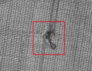
A line-scan station for textile surface defects
The lighting reveals the feature; synchronized material travel turns the line into a useful image.
- Proposed camera2048 pixels · mono
- Interfaz de lenteM42 × 1 · 12 mm flange
Fasteners and precision machining · Gauging
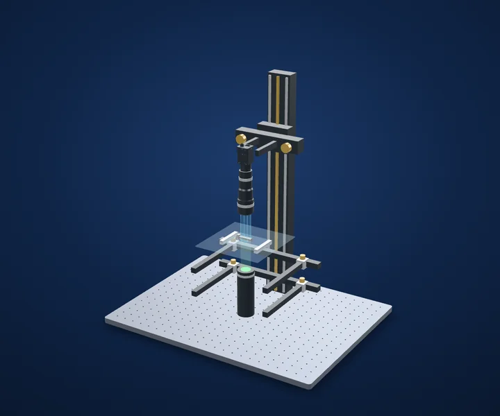
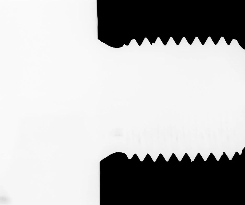
Screw thread pitch with telecentric optics
Stabilize scale and edge contrast before judging a tolerance.
- Campo de visión19.34 × 16.21 mm
- Image2456 × 2058 px
Electronics assembly · Position and angle check
Bent pins on connectors and boards
Separate real pin lean from perspective.
- Campo de visión50.46 × 37.85 mm
- Image2592 × 1944 px
Start with your inspection requirement
Make the next trial specific.
Tell us the part size, smallest defect or tolerance, available working distance, material and line speed. Include what a good part and a reject look like.
Discuss your applicationConfigurar un sistema