
Ceramic-tile patterns: spread the light before judging the surface
A ceramic tile can look uneven because the lighting is uneven. These real captures compare a straight bar with an arc bar: the broader illumination makes the decorative pattern easier to inspect across the image.
Prove lighting uniformity before classifying a decorative pattern.

 Real camera capture
- Proposed light housing (spec)196 × 20.3 × 27 mm
- EvidenceReal lighting-lab captures
- Camera (proposed)2448 × 2048 monochrome
- Field (derived proposal)84.46 × 70.66 mm
Explore it in 3D

Camera and available lens CAD are published models. Lens and light envelopes use printed dimensions. The linked station uses its published base size and column height; carriage, brackets, fittings, parts and spacing are illustrative. Confirm load, travel, fasteners and clearances before ordering. Light paths explain the arrangement and do not simulate optical performance. The part geometry is illustrative and is not reconstructed from the camera image. The proposed field is derived from the printed lens magnification and camera pixel dimensions; actual coverage and focus need a bench check. Representative part geometry is illustrative, not reconstructed inspection evidence.
Lighting application-lab image sheet
What the camera saw
Cropped from the source test sheet; original test annotations are retained. Captures are not generated or enhanced. Drag a comparison slider, or open any image full size.

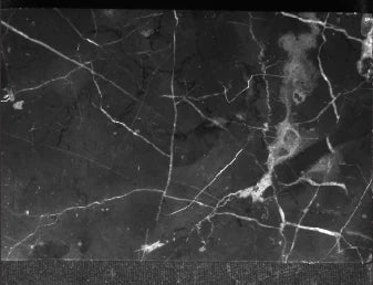
Arc bar: White arc bar: the pattern remains more visible across the captured field.
The challenge
Natural-looking veins and a reflective glaze make it easy to confuse a brightness gradient with a surface change. A small bright patch can leave useful edges dark.
How it was solved
The sheet compares white LS-BAR-0664 and white LS-BAR-1069. The latter capture shows a more even bright field across the patterned surface.
The proposed rig uses one arc bar, a monochrome camera and macro lens on the catalog test station. Part size, light angle and working distance in the scene are illustrative.
Why it works
- 1
Illumination spread controls which regions remain usable under one exposure.
- 2
The printed sheet describes a larger, more uniform spot with the arc bar. Neither image is a labelled crack dataset: the visible veins must not be reported as damage.
Lighting application-lab image sheet
Evidence you can inspect
The arc-bar capture shows the veined surface with a more even brightness distribution.
The sheet describes a larger and more uniform spot; no quantitative uniformity or defect-size result is supplied.
A lighting application-lab demonstration. The source supplies no customer deployment, defect-size limit, repeatability study or production false-call data. Proposed camera, lens, field, mounting and spacing are not the original tested system.
From image contrast to a production decision
What to validate on your part
- 01
Map the field
Capture a neutral target and the actual glaze at the centre and corners without auto exposure.
- 02
Separate pattern and damage
Include acceptable decorative veins and confirmed scratches or chips before defining rejection rules.
- 03
Vary the finish
Repeat with glossy and matt batches and the expected part height and tilt variation.
From the demo to your test bench
Parts in this setup
 LightTested
LS-BAR-1069
Arc bar light, 196 x 20.3 x 27 mm (LS-BAR-1069)
Arc bar used in the clearer capture; printed housing 196 × 20.3 × 27 mm.
$239.00
In proposed setup
 LightTested
LS-BAR-0664
High luminance bar light, 262 x 36 x 26 mm (LS-BAR-0664)
Straight bar used in the comparison; printed housing 262 × 36 × 26 mm.
$289.00
Separate test / alternative
 CameraOur pick
MV-CS050-10GM(NPOE)
Hikrobot MV-CS050-10GM(NPOE) 5 MP GigE area scan camera, IMX264, Gen 2 basic version, Mono, Without PoE
5 MP monochrome global-shutter camera, 2448 × 2048 pixels, 3.45 µm pixels and C-mount. Proposed for a bench contrast trial; the source does not identify its camera. Requires separate camera power; this NPOE model does not support PoE.Not available in the United States. Available for delivery to other countries.
$819.00
In proposed setup
 LensOur pick
LS-FFL-1454
16mm, F2.8, 1.1", C-mount, Macro lens (52 mm (-0.25X) to 546 mm (-0.03X)) (LS-FFL-1454)
16 mm C-mount macro lens; its printed 0.1x at 152 mm working distance gives a derived 84.46 × 70.66 mm field on the proposed camera. Confirm coverage, focus and the required smallest feature.
$319.00
In proposed setup
 Camera test stationOur pick
LS-MNT-0097
Camera stand with XZ adjustment and glass tray, height 600 mm (LS-MNT-0097)
600 mm column, 600 × 450 mm breadboard, XZ adjustment, glass tray and two lighting holders as listed. Proposed bench fixture; confirm loads, travel and camera/lens clamps.
$629.00
In proposed setup
"Tested" identifies the part named in the source. "Our pick" is a proposed alternative or supporting part. Confirm colour, optics, controllers, power supplies, cables and mounting before ordering.
The set-up
| Lighting evidence | Application-lab source captures |
|---|---|
| Camera and lens | Proposed catalog components; source camera unspecified |
| Proposed field (derived) | 84.46 × 70.66 mm at 0.1x |
| Lens working distance (spec) | 152 mm at the listed magnification |
| Mounting (proposed) | LS-MNT-0097 · 600 mm station, glass tray and two lighting holders |
Mount the optics with intent
The station is an optical test bench, with its two lighting holders included in the catalog listing. The 3D column and base follow the published height and footprint. Carriages, clamps and part supports are schematic: confirm camera screw pattern, lens support, light fasteners, permissible load and actual travel before ordering.
Complete the electrical system
Select a controller against the exact light voltage, drive mode and power, then confirm camera data/power/I/O cables and a suitable PC. These are not silently added to the proposed optical kit.
Build this system
Start from this setup, adapt it to your part.
The configurator opens with this study's camera, lens, light and station picked. Swap any part, check fit and price, then buy or ask for a quote.
Camera and available lens CAD are published models. Lens and light envelopes use printed dimensions. The linked station uses its published base size and column height; carriage, brackets, fittings, parts and spacing are illustrative. Confirm load, travel, fasteners and clearances before ordering. Light paths explain the arrangement and do not simulate optical performance. The part geometry is illustrative and is not reconstructed from the camera image. The proposed field is derived from the printed lens magnification and camera pixel dimensions; actual coverage and focus need a bench check. Representative part geometry is illustrative, not reconstructed inspection evidence.
Plastics, rubber and ceramics
Related case studies

 Plastics, rubber and ceramics
Ceramic glaze appearance under polarized light
Stabilize glare and colour processing before assigning a surface threshold.MethodWhite polarized ring illuminationExplore the study

 Plastics, rubber and ceramics
Comb tooth and gap inspection
Choose sampling for the smallest gap that must remain open.MethodWhite parallel backlightExplore the study

 Plastics, rubber and ceramics
Material swatches under two lighting conditions
Compare the material against a controlled reference, not a changing capture setup.Proposed light housing (spec)162 × 36 × 26 mmExplore the study
Make the next trial specific.
Tell us the part size, smallest defect or tolerance, available working distance, material and line speed. Include what a good part and a reject look like.
About this case study: the photos and camera images come from the application laboratory of the maker of the lighting and optics we sell, imaged on the parts shown; your results depend on your part, camera and set-up. This is an application-lab study, not a LumaSpec customer deployment. Source figures are reported results; proposed components require a fresh trial. The 3D scene illustrates the arrangement and does not simulate imaging performance.