
Finding bent pins on connectors and boards with telecentric backlighting
A pin that leans by a few degrees still looks fine from above and fails at the press-fit. Three tests with bi-telecentric lenses show pin rows as clean silhouettes, so angle and position come straight from the edges.
Separate real pin lean from perspective.
- 시야50.46 × 37.85 mm
- Image2592 × 1944 px
- Accuracy (as tested)< 0.019 mm
- Board test60.02 × 45.02 mm, < 0.023 mm
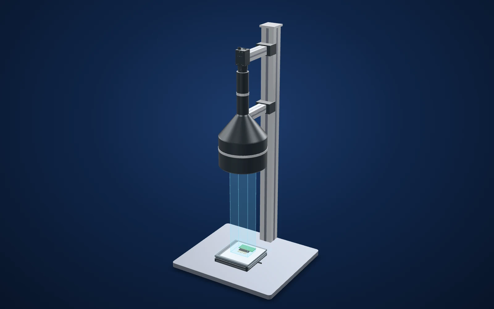 Drag to rotate · scroll to zoom
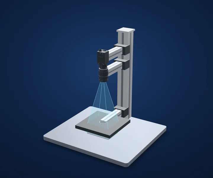
Camera and CAD lens geometry are published models where available. Light housings use printed dimensions; fixtures, parts, beam shapes and spacing illustrate the inspection principle. This is not an optical simulation or a dimensioned installation drawing.
Evidence you can inspect
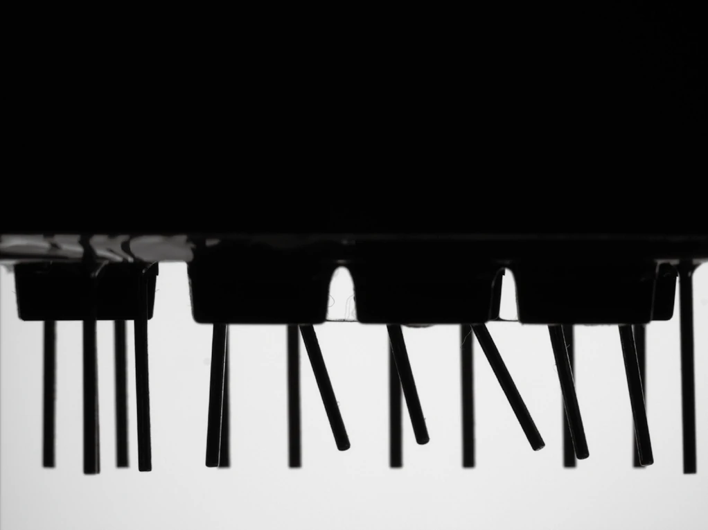
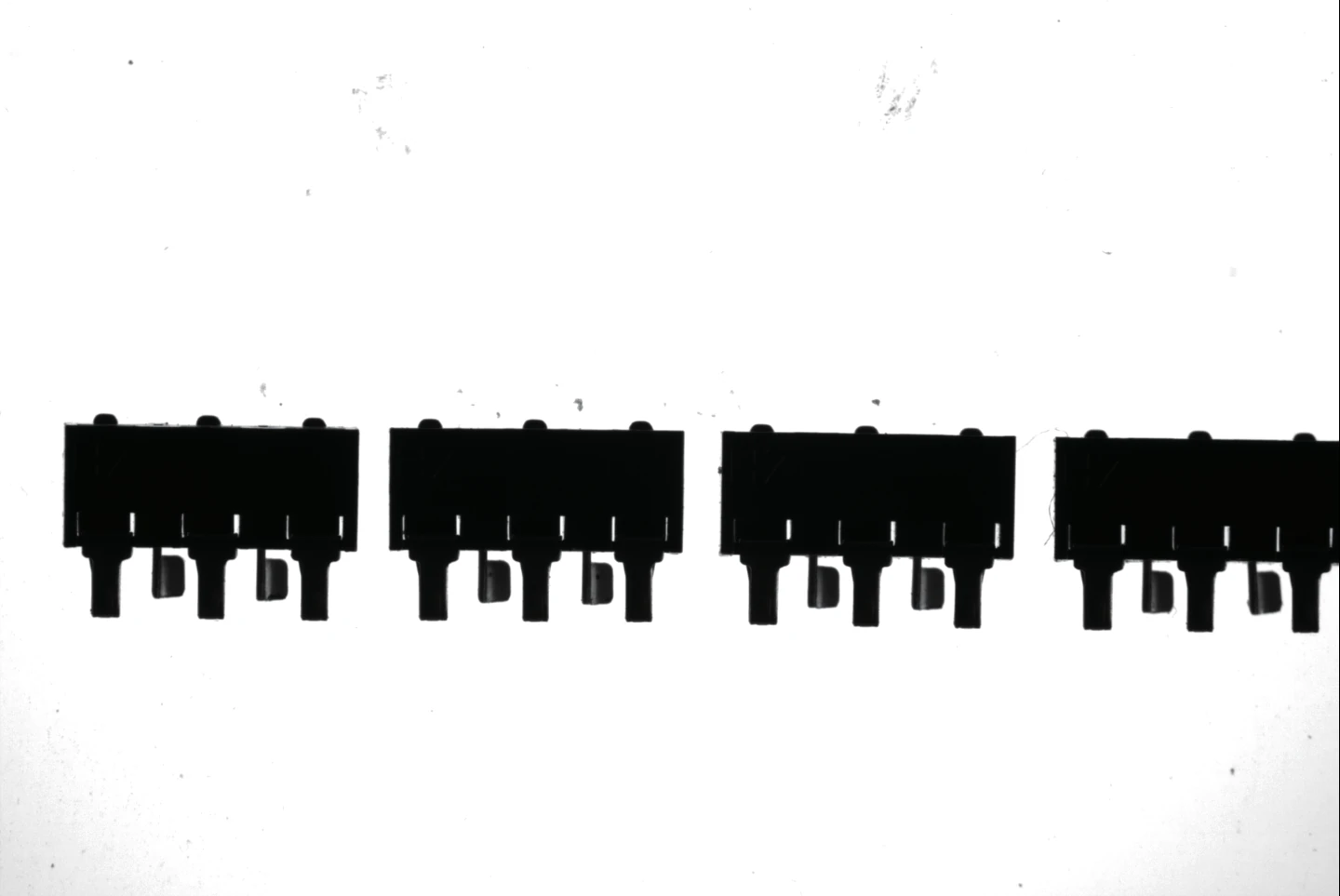
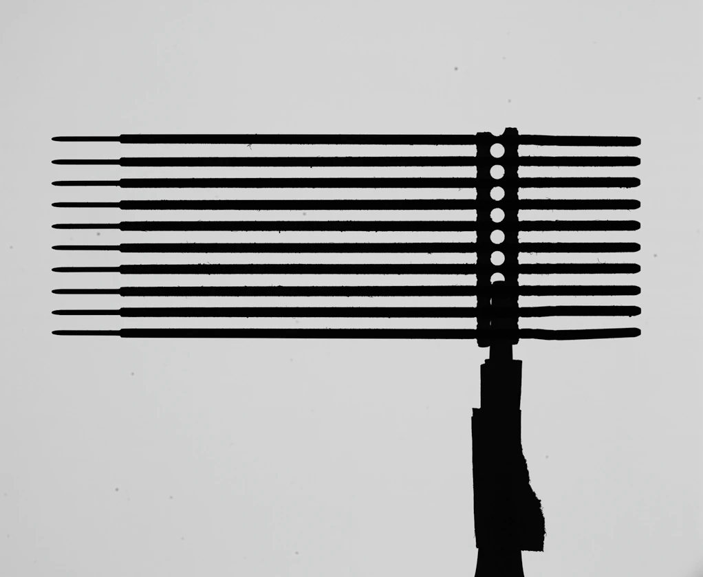
The three captures show backlit pin outlines, including visibly leaning pins.
The sheets report <0.019 mm, <0.023 mm and <0.04 mm for different camera/field combinations.
The camera and AL lens in the proposed board kit are alternatives. Validate their sampling and field on your fixture.
What the camera saw
Cropped from the source test sheet; original test annotations are retained. Captures are not generated or enhanced. Drag the comparison slider or use the image buttons.
The challenge
Pins are thin, shiny and close together. Lit from the front they flare and merge; seen through a standard lens, pins at the edge of the image lean outwards (parallax), which looks exactly like the bend you are trying to find.
The check has to measure the pin tip position and the lean of every pin across the whole row in one image.
How it was solved
Connector row: LS-VCM125-64-AL (0.113x) over a flat backlight. Field 50.46 × 37.85 mm at 2592 × 1944 px, accuracy under 0.019 mm.
Board header pins: the sheet identifies the LS-VCM230-120 with a backlight, a 60.02 × 45.02 mm field, and reports <0.023 mm. The current AL lens below is a proposed alternative rather than the exact named test lens.
Pins on a machined part: the source names the LS-VCM110-120 and a collimated light, mounted vertically. It reports an 81.62 × 81.62 mm field at 2048 × 2048 pixels and <0.04 mm.
Why it works
- 1
Telecentric optics reduce perspective differences across the field, helping distinguish pin lean from imaging geometry.
- 2
Backlighting separates the pin outlines from the background, providing edges for a position or angle check.
- 3
The quoted values belong to three separate test configurations. One proposed kit does not reproduce every test field or performance.
What to validate on your part
A useful sample image is the starting point. These are the checks that turn the concept into a defensible inspection.
- 01
Define the reject
Specify tip displacement, lean angle and the smallest gap that must remain visible.
- 02
Test the complete row
Check edge-of-field pins and pins at different depths and heights.
- 03
Include fixture motion
Repeat loading and triggering with good and deliberately bent samples.
The set-up and the parts
| Cameras (tests) | 5 MP 2592 × 1944 px; 4 MP 2048 × 2048 px (1") |
|---|---|
| 렌즈 | Bi-telecentric 0.113x / 0.095x / 0.138x |
| 조명 | Flat backlight; collimated light |
| 작동 거리 | 187 mm / 280 mm / 280 mm (lens specs) |
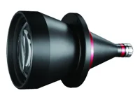
Current AL lens, 0.095x. The board sheet names the non-AL LS-VCM230-120; this alternative requires field and working-distance validation.
$2,609.00In proposed setup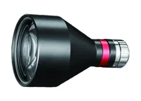
0.113x for 1/2.5" sensors; used for the connector row.
$1,649.00Separate test / alternative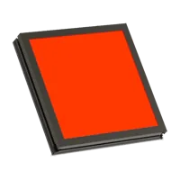
Flat backlight with a 100 × 100 mm emitting area, larger than the 60 × 45 mm field so the edges stay bright.
$109.00In proposed setup
Collimated light with a 120 mm beam, for the vertical machined-part test.
$889.00Separate test / alternative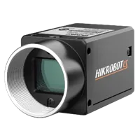
5 MP 2/3" monochrome; fills the LS-VCM230-120-AL's 2/3" image circle.
$819.00In proposed setup"Tested" identifies the part named in the source. "Our pick" is a proposed alternative or supporting part. The quote includes only cards marked "In proposed setup", with the quantities shown; other test arrangements are separate. Confirm colour, optics, controllers, power supplies, cables and mounting before ordering.
About this case study: the photos and camera images come from the application laboratory of the maker of the lighting and optics we sell, imaged on the parts shown; your results depend on your part, camera and set-up. This is an application-lab study, not a LumaSpec customer deployment. Source figures are reported results; proposed components require a fresh trial. The 3D scene illustrates the arrangement and does not simulate imaging performance.
More case studies
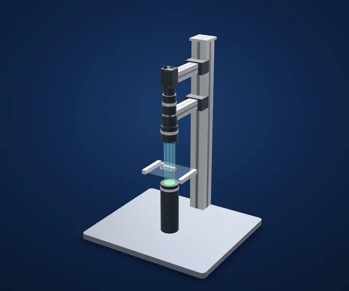
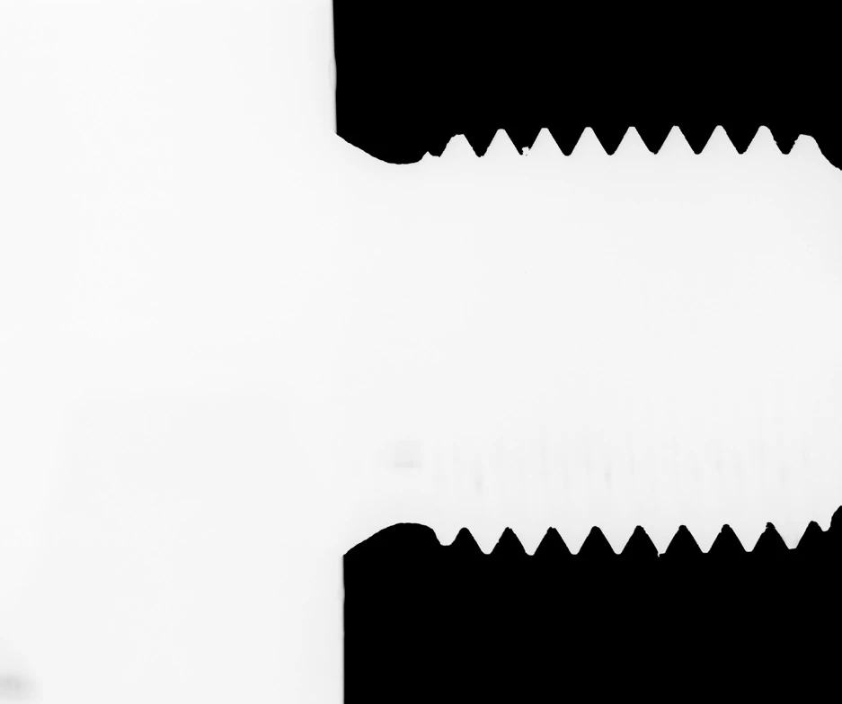
Screw thread pitch with telecentric optics
Stabilize scale and edge contrast before judging a tolerance.
- 시야19.34 × 16.21 mm
- Image2456 × 2058 px
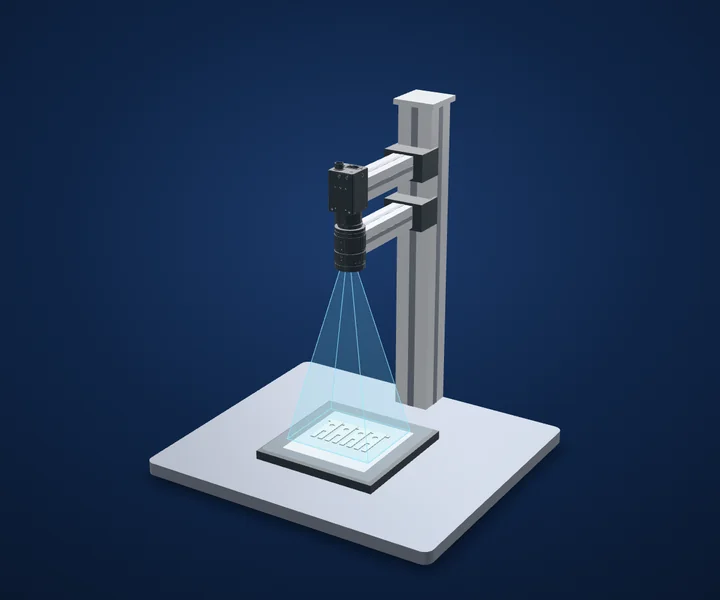
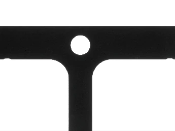
Stamped-metal terminal contours
Use a silhouette when the requirement is shape.
- Test lightWhite thin-panel backlight
- Housing (spec)140 × 140 × 9.5 mm
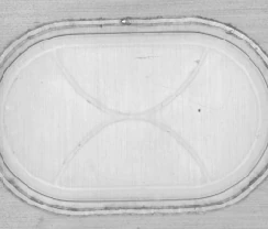
Battery welds and tabs
Control what shiny metal reflects.
- 조명Flat dome, 100 × 100 mm emitting
- 크기140 × 140 × 11.5 mm
Make the next trial specific.
Tell us the part size, smallest defect or tolerance, available working distance, material and line speed. Include what a good part and a reject look like.
Discuss your application시스템 구성