
Battery weld marks and tabs: controlling reflections with diffuse light
Laser weld marks on battery cases are faint, the metal is frosted and the tabs are mirror-bright. Side-by-side tests show how a flat dome light turns an unreadable weld into a clean outline, and why the camera hole in a dome matters on a shiny tab.
Control what shiny metal reflects.
- 光Flat dome, 100 × 100 mm emitting
- サイズ140 × 140 × 11.5 mm
- ワーキングディスタンスClose, under the camera
- ResultWeld outline readable after the change
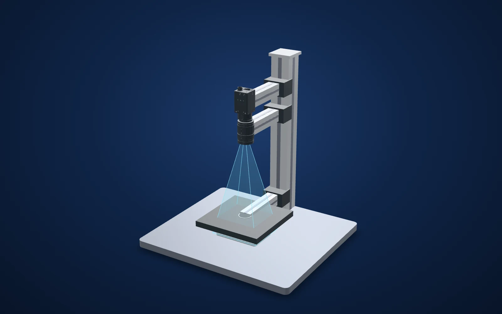 Drag to rotate · scroll to zoom
Camera and CAD lens geometry are published models where available. Light housings use printed dimensions; fixtures, parts, beam shapes and spacing illustrate the inspection principle. This is not an optical simulation or a dimensioned installation drawing.
Evidence you can inspect
The supplied lighting comparisons show a clearer weld outline and a change in the reflected dark aperture on a shiny tab.
The source compares lighting arrangements; it does not report weld strength, penetration or a detection rate.
Surface appearance is evidence for an imaging trial. It cannot establish weld integrity beneath the surface.
What the camera saw
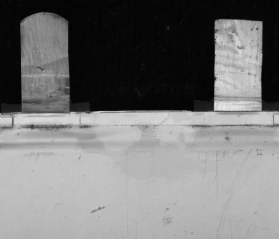
Cropped from the source test sheet; original test annotations are retained. Captures are not generated or enhanced. Drag the comparison slider or use the image buttons.
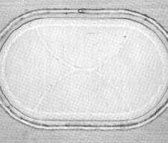
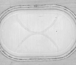 Shadowless lightFlat dome
Flat dome: Flat dome (LS-2LFX100-C): the weld outline is clear and even.
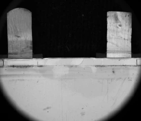
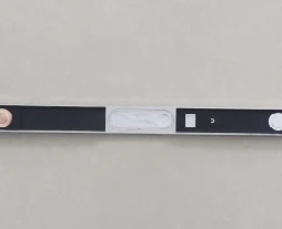
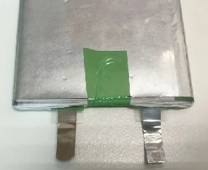
 Round domeSquare, hole sized to the part
Square, hole sized to the part: Square shadowless light with the centre hole sized to the part (made to order): no dark spot.
The challenge
A weld seam on an aluminium case is a low-relief mark on a frosted surface. A plain shadowless light scatters off the frosting and the seam disappears into texture.
The tabs are the opposite problem: polished metal mirrors whatever is above it, including the dark camera hole of a dome light.
How it was solved
Weld marks: the test first used the LS-LFX100 shadowless light, where the frosting hid the surface detail. Changing to the LS-2LFX100-C flat dome, which lights the part evenly from a wide range of angles, strengthened the surface lighting and brought the weld outline out clearly.
Tabs: under the LS-DM120-W dome the tab is evenly lit, but the dome's small centre hole shows as a dark spot reflected in the metal. A square shadowless light with its centre hole sized to the long side of the part removes it; we build that to order.
Why it works
- 1
Broad diffuse illumination changes the reflection pattern on frosted metal. In this comparison, the flat dome makes the weld outline easier to distinguish.
- 2
Only 11.5 mm tall, so it fits between the lens and the part on a crowded line.
- 3
On mirror-like parts, anything above the part is in the picture: size the camera hole or move it off the region you measure.
What to validate on your part
A useful sample image is the starting point. These are the checks that turn the concept into a defensible inspection.
- 01
Keep good texture in the trial
Include normal frosting, finish variation and acceptable weld marks.
- 02
Challenge the reflection
Vary tab tilt and check for the camera-hole reflection across the full part.
- 03
Confirm the inspection requirement
Separate visible surface defects from weld-quality checks requiring other methods.
The set-up and the parts
| Weld light | Flat dome (LS-2LFX100-C), white |
|---|---|
| Tab light | Dome (LS-DM120-W) or square shadowless, made to order |
| カメラ | Area scan, mounted straight down through the light |
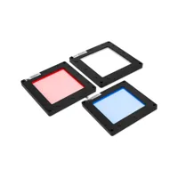
Flat dome, 100 × 100 mm emitting area, 140 × 140 × 11.5 mm.
$329.00In proposed setup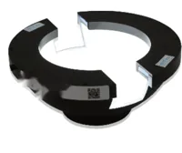
Dome, 120 mm outside, 30 mm centre hole, 52 mm high.
$359.00Separate test / alternative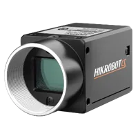
5 MP 2/3" monochrome: about 41 µm per pixel across a 100 mm field (100 mm / 2448 px).
$819.00In proposed setup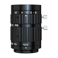
16 mm macro lens, 0.25x to 0.03x; a 100 mm field on a 2/3" sensor needs about 0.085x.
$319.00In proposed setup"Tested" identifies the part named in the source. "Our pick" is a proposed alternative or supporting part. The quote includes only cards marked "In proposed setup", with the quantities shown; other test arrangements are separate. Confirm colour, optics, controllers, power supplies, cables and mounting before ordering.
About this case study: the photos and camera images come from the application laboratory of the maker of the lighting and optics we sell, imaged on the parts shown; your results depend on your part, camera and set-up. This is an application-lab study, not a LumaSpec customer deployment. Source figures are reported results; proposed components require a fresh trial. The 3D scene illustrates the arrangement and does not simulate imaging performance.
More case studies
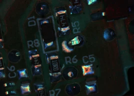
PCB solder joints with an RGB AOI light
Use lighting angle to make solder shape visible.
- 光AOI, 160 mm outside, 45 mm aperture
- 高さ55 mm
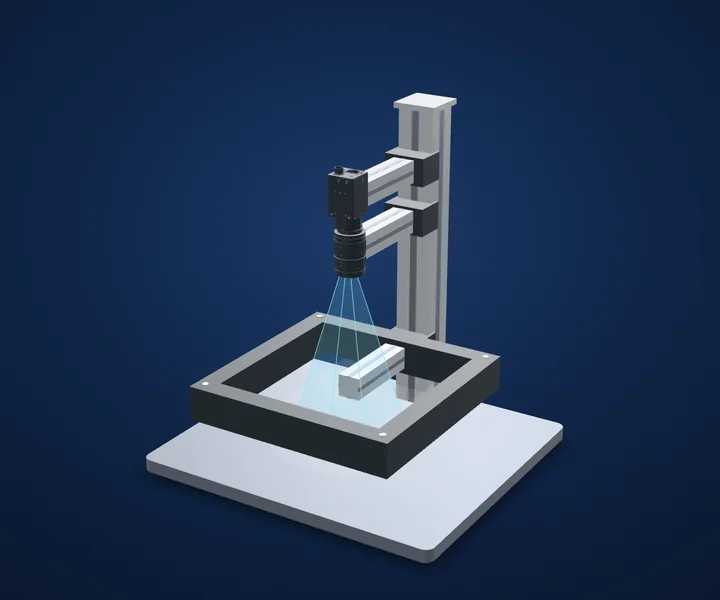
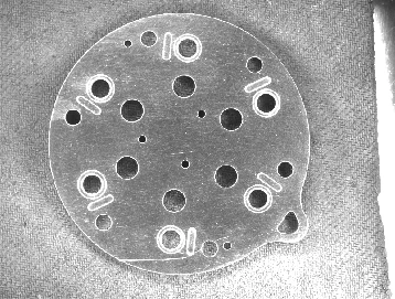
Scratches on machined metal
Choose lighting direction before adding resolution.
- Test lightFour-sided adjustable bar light
- Housing (spec)230 × 230 × 37 mm
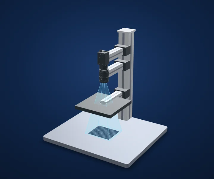
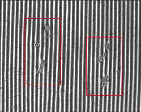
Polarizer-film defects in reflected stripes
Give a featureless surface a pattern to reflect.
- Light-to-part (as tested)100 mm
- Exposure (as tested)8,000 µs / 8 ms
Make the next trial specific.
Tell us the part size, smallest defect or tolerance, available working distance, material and line speed. Include what a good part and a reject look like.
Discuss your applicationシステム構成